

|
|
|
|
 |

|
 |
BMW Garage | BMW Meets | Register | Today's Posts | Search |
 |

|
BMW 3-Series (E90 E92) Forum
>
DIY: Make your own DEI 504D shock sensor harness
|
 |
| 03-13-2010, 05:24 PM | #1 |
|
Second Lieutenant
 20
Rep 254
Posts |
DIY: Make your own DEI 504D shock sensor harness
Ok this is going to be my first contribution to this forum, hope you guys like it. I had read the DIY on how to install the DEI 504D shock sensor in series with the OEM alarm, but the pictures are gone, and it involved either cutting or tapping into the stock wiring. I really don't want to cut my wiring, so I decided to make my own harness. I originally looked for the BMW part, but when i couldn't find it, I used SIP header's and sockets instead.
As a prerequisite, read this DIY to know which wires need to be connected to what on the alarm, after that you'll know which pins on the harness are which. Parts required: 1/16" or 3/32" heat shrink tubing (a few pieces) 1ea 1x8 .1" spacing SIP header 1ea 1 x8 .1" spacing SIP socket 8ea 3" piece of stranded wire, roughly 20-22 gauge (note I used solid core, I might make another one using stranded so it is more flexible.. solid is pretty stiff. The only problem is the connector I chose required stiffer cable to push in.) butane torch or heat gun to shrink the tubing 30-45 minutes time Parts: 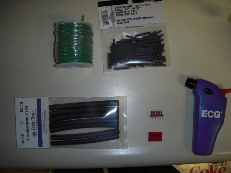 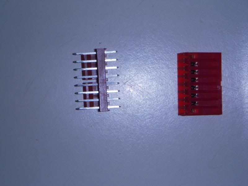  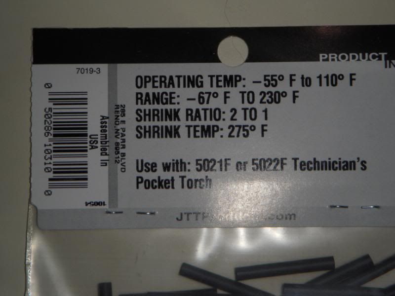 Step 1: Cut 8 3" pieces of wire 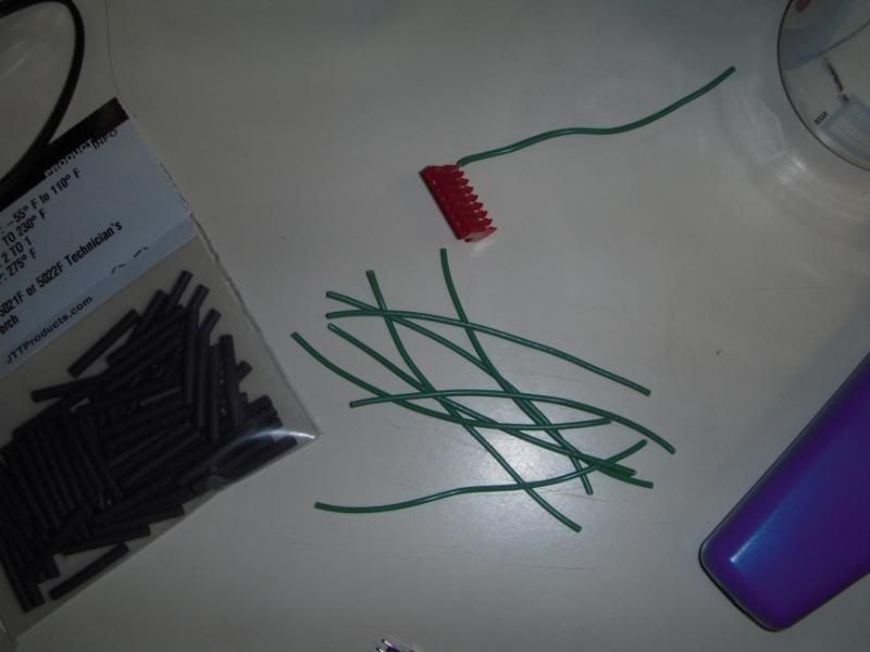 Step 2: cut off about 1/4" of the ends of your wires, as such: 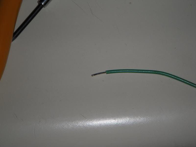 the connectors that I used were push in kind, meaning you need a punch down tool or small jewelers flat head screw driver, and something to hit it with, I used my pliers. Insert one end into the connector, as shown: 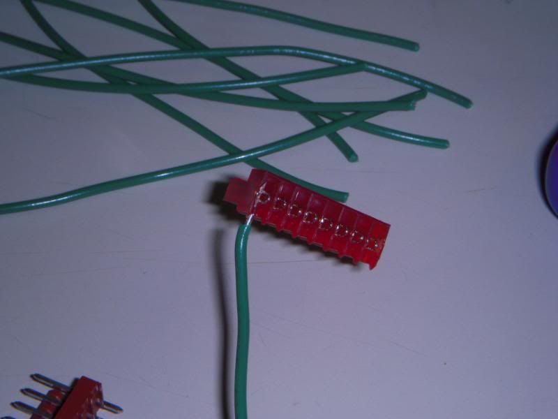 Repeat the process, using the screwdriver and hammer/pliers or punch down tool to push the wire in until it's secure. Step 3: (optional) Once you have all the wires inserted in your socket, you can optionally shrink them so they are bundled together, just make sure you know which one is which. (pin one is right side in my setup) Step 4: strip the other ends of the wire, and slide a piece of heat shrink down the end. For the 3 wires that come from the DEI module, strip these as well, and twist them to the wires you are using. Slide the heat shrink material up so it covers just the wire/connector, and heat it up. The reason I did this instead of soldering, was because solder took up too much space, and I didn't have any tools to hold the parts while i worked. Heat shrink also protects the connections from being touched by anything metal. Step 5: You're done! you should have something that looks similar to this: 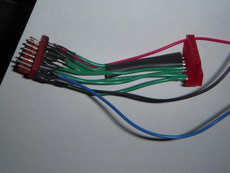 I know it looks kinda ghetto, I was trying to figure it out as I went along, and I'll probably end up redoing it with smaller heat-shrink tubing to make tighter fits. It's been a long time since I've done any manual electronics work like this, so the 2nd version will be better. Step 6: Reinstall everything... here's where I mounted my sensor. A light thump on the car with sensitivity turned up all the way makes the alarm go off, yet loud cars going by do not set it off.  Closeup: 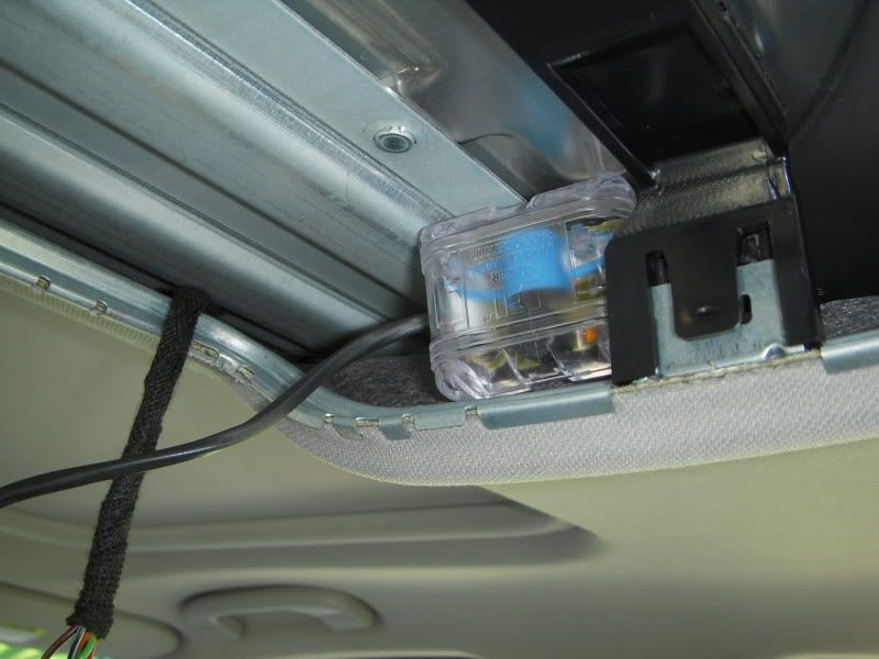 Total cost for parts was about 80 cents for the connectors, 9$ for the spool of wire (100 feet or so) and 4$ for all the heat shrink, so about 14$, however I have enough wire/tubing to make probably 30 or so of these things, so in reality its only about 1$ worth of parts to make the harness. One note: I used 3/32" tubing for the connector, when I redo it I'm going to use 1/16" tubing, as the 3/32" stuff is a tiny bit too loose. If you have any questions, please let me know  Plans for version 2: -use smaller heat shrink tubing for tighter connection, and cover all connections. - use epoxy or super glue to seal wires in to connectors as well as cover any more exposed metal. -possibly heat-shrink the entire harness once assembled for cleaner appearance.
__________________
'07 SGM + DG 335i sedan|Navi|ZPP|Rear PDC|Euphoria 6k LED interior|Matte Black Grills|OEM Blacklines|MTEC A.E's|CF Roundels|Alufelgen 19" CS7 with 15/12mm spacers
If I buy something from you please leave me feedback My Portfolio Last edited by my07_335i; 03-14-2010 at 01:01 AM.. |
| 03-13-2010, 11:31 PM | #2 |
|
New Member

0
Rep 22
Posts |
What an excellent guide! If only you'd posted it a day earlier, before I tried installing the shock sensor directly.
I think that it's important to note that the guide is useful outside of just being specific about splicing original wires -- the connectors mentioned in the other DIY simply don't work some/most of the time. Even after exposing part of the wire for both wires on each set and aligning it with the metal contact in the connector (three times), it still didn't work! I ultimately was able to get it to work by manually tying the one wire around the other (originally just to see if the unit was defective), which is obviously a temporary fix, and a shoddy one at that. In the end, the only truly reliable method for ensuring continuous contact, short of soldering, is the harness in this guide. |
|
Appreciate
0
|
 |
| Bookmarks |
|
|


