|
|
|
|
 |

|
 |
BMW Garage | BMW Meets | Register | Search | Today's Posts | Mark Forums Read |
 |

|
BMW 3-Series (E90 E92) Forum
>
Vishnu DIY: o2 simulator
|
 |
| 06-21-2008, 03:25 PM | #1 |

1736
Rep 17,960
Posts
Drives: A Lot
Join Date: Sep 2006
Location: SF Bay, CA
iTrader: (0)
Garage List 2018 Ducati Panigal ... [0.00]
2016 Mazda CX5 [0.00] 2017 Aprilia Tuono ... [0.00] 2019 BMW M2 Competi ... [0.00] 2015 BMW M5 Competi ... [10.00] 2016 Ducati XDiavel S [0.00] 2016 AMG GT S [0.00] 2011 Ferrari 458 It ... [0.00] 2017 Charger Hellcat [0.00] 2015 KTM Super Duke ... [0.00] 2016 KTM RC390 [0.00] |
Vishnu DIY: o2 simulator
Ok guys,
This is a first in a line of DIY guides that we will be possting. In this guide, we'll be showing how to make an o2 simulator. This is specifically used for catless cars. Off-road race cars, of course. This mod is not emissions legal and using it on the street can subject you to fines. Also, we take no responsibility for any damage that may arise, directly or indirectly, from this modification. Those disclaimers aside, this mod will take you about 10 minutes and cost you about $2. A lot better than paying $100+ for o2 sim boxes that do the same thing. What does an o2 simulator do? Before we get to that, first let's see what a standard o2 sensor signal looks like. Measured on a scope, it will look like this: 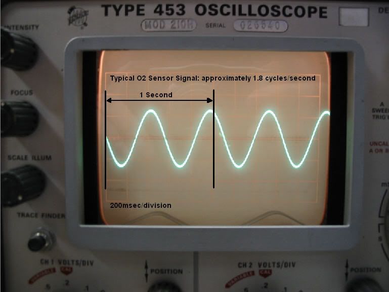 On a stock car, with stock cats, the signal varies between ~0.7 to ~0.4 volts during cruise conditions. However, once test pipes are installed, the range increases to ~0.9 to ~0.4 volts. This extra swing is what induces the catalyst inefficiency limp/code. So the idea behind the o2 sim is to reduce the voltage swing back down to stock levels. This is done by something called a voltage divider. This is also the same concept behind MAP attenuators (JB and SSTT). You can read more about voltage dividers here: http://en.wikipedia.org/wiki/Voltage_divider What a voltage divider does is reduce voltage by a fixed %. This % is dictated purely by resistor choice. In this case, we want to reduce the max voltage by approx 80%. So we choose to use a 10k ohm and a 2.2k ohm resistor (10/(10+2.2))=82%. Other combinations of resistors can be used to get the same effect. So that's the theory. In the next post, we'll go over how to actually do it. cheers, shiv Last edited by OpenFlash; 06-21-2008 at 04:31 PM.. |
|
|
| 06-21-2008, 03:50 PM | #5 | |
|
Major

78
Rep 1,232
Posts |
Quote:
 |
|
|
Appreciate
0
|
| 06-21-2008, 03:55 PM | #6 |
|
1736
Rep 17,960
Posts
Drives: A Lot
Join Date: Sep 2006
Location: SF Bay, CA
iTrader: (0)
Garage List 2018 Ducati Panigal ... [0.00]
2016 Mazda CX5 [0.00] 2017 Aprilia Tuono ... [0.00] 2019 BMW M2 Competi ... [0.00] 2015 BMW M5 Competi ... [10.00] 2016 Ducati XDiavel S [0.00] 2016 AMG GT S [0.00] 2011 Ferrari 458 It ... [0.00] 2017 Charger Hellcat [0.00] 2015 KTM Super Duke ... [0.00] 2016 KTM RC390 [0.00] |
What you will need assuming you already have a PROcede PnP harness:
1) One 10k ohm resistor 2) One 2.2k ohm resistor 3) 10 inch section of 22 gauge wire 4) Soldering ability 5) Wire cutters/strippers 6) Shrink wrap or electrical tape Step 1 First locate the rear o2 wires on the PnP harness. They are the two wires that are color coded black: 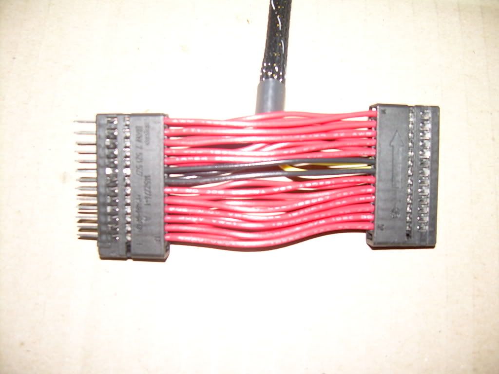 Step 2 Cut, strip and join the wires as follows. Sorry for the rotten pic. Basically, you are taking out a 1/2 section from the center of both black wires. On the side with the male subconnector (left in pic), you only will be using one of the two wires. Pick one and strip the end. On the side with male subconnector (right in pic), you will need to strip the ends of both wires and twist them together. 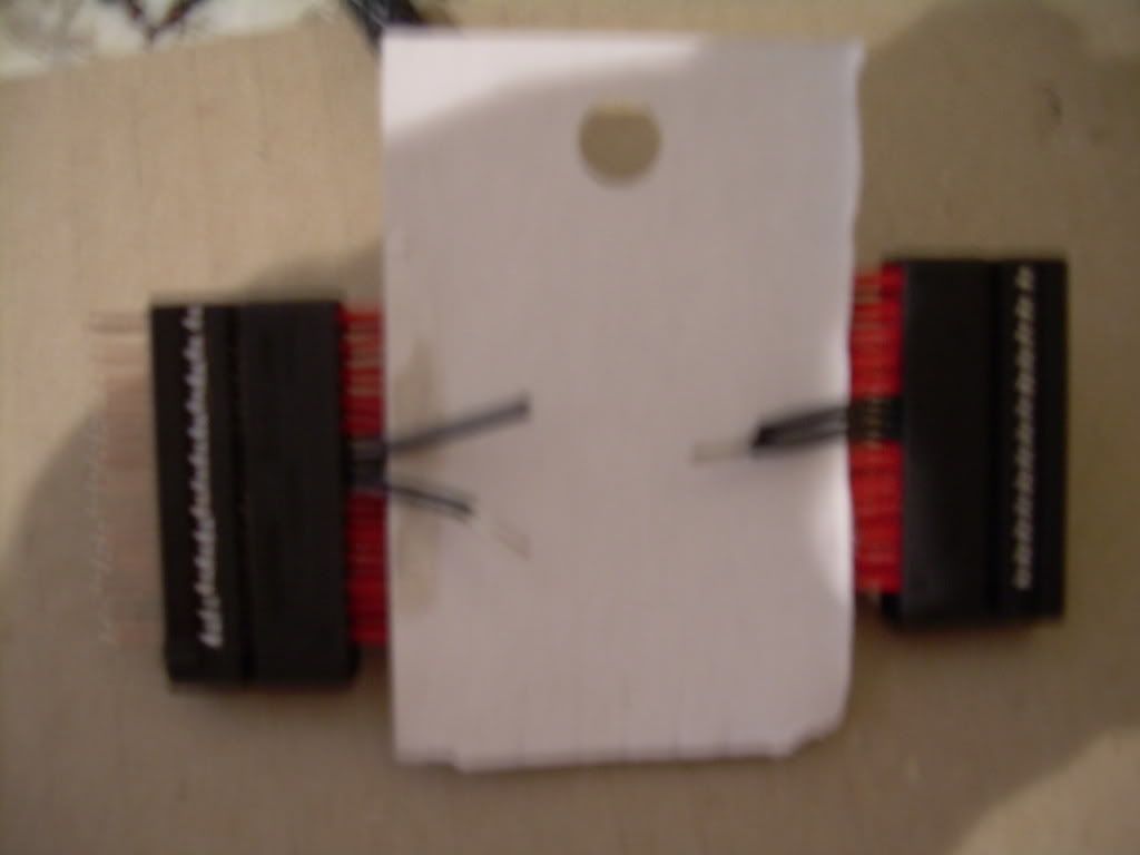 Step 3 Take the 2.2k ohm resistor and join the single wire on the left to the joint wires on the right. Solder these connections. 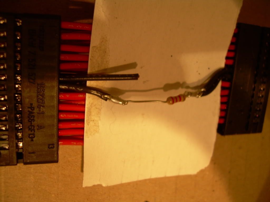 Step 4 Take the 10k ohm resistor and wire it up as such: 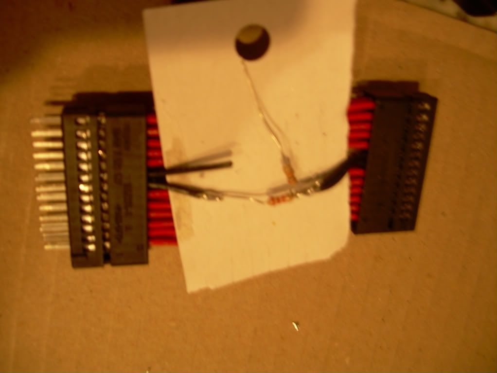 Step 5 Next, add a section of wire to the other end of the 10k ohm resistor. Join the other end of that wire to the PROcede harness's ground wire (not shown). And then cover up the exposed resistors with shrink wrap or electrical tape. You should also cover up the exposed wire end with electrical tape (not shown). 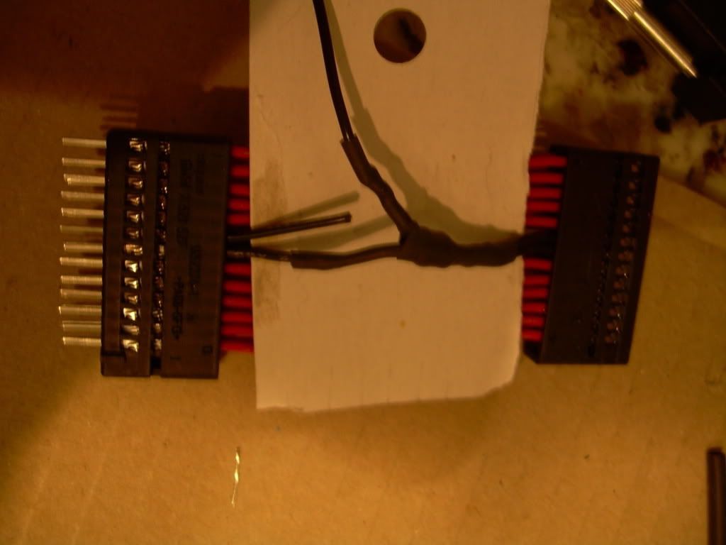 Step 6 Re-install the harness and go for a drive. You should not trip the catalyst inefficiency code anymore. And you should also get catalyst system readiness after a day or so of driving. Conclusion What you basically did with this DIY is take one of the two o2 signals, used a voltage divider to scale down the voltage output and fed this new-and-improved signal to both ECU signal inputs. The same job can be done even if you don't have a PROcede PnP harness. You just need to locate the same two wires in the factory harness. They are on the small black subconnector. Pin 19 and 20. They are yellow/white wires, IIRC. NOTE: This mod is only for those who are running fully cat-less and throwing P0420 and P0430 codes. If this does apply to you, there is no need to do this mod. Cheers shiv Last edited by OpenFlash; 06-21-2008 at 04:28 PM.. |
|
Appreciate
0
|
| 06-21-2008, 04:00 PM | #7 |
|
1736
Rep 17,960
Posts
Drives: A Lot
Join Date: Sep 2006
Location: SF Bay, CA
iTrader: (0)
Garage List 2018 Ducati Panigal ... [0.00]
2016 Mazda CX5 [0.00] 2017 Aprilia Tuono ... [0.00] 2019 BMW M2 Competi ... [0.00] 2015 BMW M5 Competi ... [10.00] 2016 Ducati XDiavel S [0.00] 2016 AMG GT S [0.00] 2011 Ferrari 458 It ... [0.00] 2017 Charger Hellcat [0.00] 2015 KTM Super Duke ... [0.00] 2016 KTM RC390 [0.00] |
Next Vishnu DIY: How to build a boost controller (SSTT/JB-like device) for under $2
|
|
Appreciate
0
|
| 06-21-2008, 04:26 PM | #10 |
|
Colonel

208
Rep 2,558
Posts |
Yeahhh... for some reason I'm just not comforted by the sound of the coolant pump alone... I want the whole damn engine on for a minute or two after I walk away from the car... =P Guess I just need to get used to it...
__________________
'07 Space Gray 335i coupe - R.I.P.
 COBB ProTuned | AMS | CP-e | BMS | Quaife |
|
Appreciate
0
|
| 06-21-2008, 04:27 PM | #11 | |
|
Major General
 153
Rep 5,780
Posts |
Quote:
  |
|
|
Appreciate
0
|
| 06-21-2008, 04:29 PM | #13 | |
|
1736
Rep 17,960
Posts
Drives: A Lot
Join Date: Sep 2006
Location: SF Bay, CA
iTrader: (0)
Garage List 2018 Ducati Panigal ... [0.00]
2016 Mazda CX5 [0.00] 2017 Aprilia Tuono ... [0.00] 2019 BMW M2 Competi ... [0.00] 2015 BMW M5 Competi ... [10.00] 2016 Ducati XDiavel S [0.00] 2016 AMG GT S [0.00] 2011 Ferrari 458 It ... [0.00] 2017 Charger Hellcat [0.00] 2015 KTM Super Duke ... [0.00] 2016 KTM RC390 [0.00] |
Quote:
 You are correct sir. Original post edited accordingly. I went to the bathroom for confirmation as well. You are correct sir. Original post edited accordingly. I went to the bathroom for confirmation as well. |
|
|
Appreciate
0
|
| 06-22-2008, 08:15 AM | #14 |
|
Whats that smell?
145
Rep 1,790
Posts |
Hamburgers and Hot Dogs
One more thing you may want to comment on is how certain folks need "stronger" sims vs others. Does this mean the waveform in those vehicles has a larger amplitude? If so, is there an easy DIY for an adjustable sim. Potentiometer type I suppose. |
|
Appreciate
0
|
| 06-22-2008, 12:59 PM | #16 |
|
Lieutenant Colonel
 136
Rep 1,954
Posts
Drives: 2020 X3M Competition
Join Date: Mar 2007
Location: Los Angeles, CA
|
Will the DP loom that was provided with the v2-v3 upgrade work in this application?
__________________
2020 F97 X3M Competition (current) - 2018 F80 M3 Competition - 2015 F82 M4 - 2012 E82 135i - 2010 E92 335i - 2007 E92 335i
|
|
Appreciate
0
|
| 06-22-2008, 01:04 PM | #17 |
|
Whats that smell?
145
Rep 1,790
Posts |
tek, I sort of dabbled on that subject here....
http://www.e90post.com/forums/showthread.php?t=151264 |
|
Appreciate
0
|
| 06-22-2008, 06:59 PM | #19 | ||
|
اوليسيس
196
Rep 4,678
Posts |
Quote:
__________________
Quote:
|
||
|
Appreciate
0
|
| 06-22-2008, 09:03 PM | #21 | |
|
1736
Rep 17,960
Posts
Drives: A Lot
Join Date: Sep 2006
Location: SF Bay, CA
iTrader: (0)
Garage List 2018 Ducati Panigal ... [0.00]
2016 Mazda CX5 [0.00] 2017 Aprilia Tuono ... [0.00] 2019 BMW M2 Competi ... [0.00] 2015 BMW M5 Competi ... [10.00] 2016 Ducati XDiavel S [0.00] 2016 AMG GT S [0.00] 2011 Ferrari 458 It ... [0.00] 2017 Charger Hellcat [0.00] 2015 KTM Super Duke ... [0.00] 2016 KTM RC390 [0.00] |
Quote:
shiv |
|
|
Appreciate
0
|
| 06-23-2008, 01:14 AM | #22 |
|
Lieutenant
 4
Rep 479
Posts |
Hmm, if I was to do this, I would do the following correct:
1. Remove wire 19 and 20 from the small black sub-connector. 2. Cap either wire 19 or 20. 3. Connect which ever is left from #2, either wire 19 or 20, to the voltage divider. 4. Connect the output wire of the voltage divider to both pins 19 and 20. Am I missing anything here, well aside from going to Fry's and buying the resistors. |
|
Appreciate
0
|
 |
| Bookmarks |
| Thread Tools | Search this Thread |
|
|