Preface: I've embedded this lengthy post with many links hoping to assist those as inexperienced as I was with the E9x when I bought my car. There's much here but it won't turn you into a mechanic! That said, this project can be done by anyone with a level of determination, a nearby Sears, and good credit.
You'll learn much though your ride may be laid up awhile - not being my daily driver, I was able to take whatever time was needed - it was a pleasure doing work at my leisure, well over a month on jack stands from start to finish. Accomplished BMW pilots have done it over a weekend. Do these mods if you can - you won't regret it - my best to ya'll!
Contents:
Beginnings
DO'S and DON'TS
Raise the vehicle on jack stands
Remove E93 undercarriage braces
R&R front wishbones and tension struts
R&R front shocks/springs [struts]
R&R front sway bar
R&R strut brace - engine compartment
Drop the rear subframe but not the exhaust
R&R rear subframe bushings
R&R rear sway bar
R&R rear wishbones and guide rods
R&R rear springs, shocks, camber arms; toe arms
Finishing touches
Appendix A - Wheel normal ride height
Appendix B - Torque Values
BEGINNINGS
It all started when I drew inspiration from replacing my vile Bridgestone Potenza RFT's w/Michelin PS2's -- like taking off a tight shoe, my life improved.
Boldened, I purchased a
Wavetrac LSD and had Sonic Motorsports do the install. I immediately felt the difference - I can feel it while moving slowly down my driveway - found major performance boost in curves, especially accelerating.
I searched, found, and read the Classics....
Speediance....
1fastBMW....
jprandkpr....a host of others; my future became clear....total suspension replacement and M strut brace mod.
One thing stood out: There are just about NO examples of E93 suspension mods.
I purchased a
Bentley manual....thus began my adventure. After some study, late last year, I went ALL-IN.
Ordered:
Street/School kit from Ground Control, a few miles East of Sacramento. Added end links for front sway to that order.
Ordered: M control arms, M sways, M rear subframe bushings, M strut brace, rear toe arms, and rented a bushing install tool from
HP Autowerks in Santa Barbara.
Ground Control took awhile as rear E93 shocks are not the same as other models....the top mechanism adds 400 lb. Not having any in stock, I waited for Koni to make 'em in Holland and ship to Ground Control....this was unexpected, but to do it right....
Toe arms were hard to come by. But, HP Autowerks was able to supply
their new toe arms fresh from the anodizing shop exactly when I happened to need 'em - good to go!
WARNING: MY SETUP IS PREDICATED ON THE PRESENCE OF A LIMITED SLIP DIFFERENTIAL - UNPREDICTABLE RESULTS MAY OCCUR IF NOT INSTALLED - GROUND CONTROL NEEDS M SWAYS WHICH NEED A LSD FOR BEST OPERATION
DO'S and DON'TS
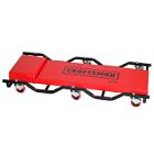
DO acquire a comfortable creeper. I used this Craftsman 40" padded unit:
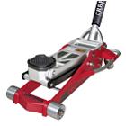
 DO use at least 2 floor jacks for this project.
 You'll thank yourself for that. I used this Aluminum Craftsman, pricey and works no better, just liked it; Milwaukee by far the best if used often over time:
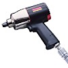
 DO use an air driven 1/2" impact wrench.
 I used this Craftsman, an indispensable tool:
 DO use a quality 1/2" torque wrench.
 3/8" will work but the longer handled 1/2" gives you more leverage; power. I used this electronic Gearwrench -- beeps when target torque is reached; accurately measures and beeps on user set angle past torque as BMW requires on some bolts. Replaced my analog breakaway wrench with this -
glad I did:
![Name: Grearwrench Electronic Torque Wrench with Angle [a 50].jpg
Views: 33519
Size: 8.4 KB](https://www.e90post.com/forums/attachment.php?s=4f52d3fb1c0917873af446a78d080b5d&attachmentid=677434&d=1334768746) DO dress all bolts & studs with anti-seize - I used Permatex 81343, Ace Hardware:
DO dress all bolts & studs with anti-seize - I used Permatex 81343, Ace Hardware:
![Name: Permatex 81343 Anti-Seize Lubricant 133 [50].jpg
Views: 33323
Size: 8.5 KB](https://www.e90post.com/forums/attachment.php?s=4f52d3fb1c0917873af446a78d080b5d&attachmentid=676792&d=1334678437) DON'T depend on floor jacks to keep your ride up!
DON'T depend on floor jacks to keep your ride up! Not even close to reliable for that duty.
Use a 3+ ton jack stand at each pad. They're inexpensive -- 6-7 jack stands might be used at some points in the job. Remember to use wood between the jack stand and the point of contact to prevent damage.
![Name: 3 Ton Jack Stands [70].jpg
Views: 34517
Size: 7.0 KB](https://www.e90post.com/forums/attachment.php?s=4f52d3fb1c0917873af446a78d080b5d&attachmentid=676943&d=1334688110) DON'T completely remove a bolt with an impact wrench - turn those last threads out by hand
DON'T completely remove a bolt with an impact wrench - turn those last threads out by hand. If a bolt is removed under power it may rocket out of the impact socket with enough energy to damage the thread where it next makes contact. Not a happy occurrence....PITA to fix!
DON'T install a bolt using an impact wrench until well started in the threaded area. Always start threading in a bolt by hand - otherwise, you stand a chance of screwing up the threads. You don't want that!
____________________________
I bought this 3 ton Craftsman set on sale - floor jack & jack stands worked well; 36" creeper was crap, being 2-piece and too short for this tall boy with no dip in frame rails for shoulder room [see the creeper I used, above]:

I now see the above set as a poor value -- I've yet to use the uncomfortable creeper and the floor jack quickly became on/off....little fine control. On the up side, the jack stands work.
Recommend: Purchase a quality floor jack. Used way too much for low cost performance! $300+ might be a good ball park.
Recommend: 4 post lift
[Example] with jack so wheels can be R&R'd. Don't yet have; purchasing when I decide where can set up. Not a 'light weight' but immensely useful.
RAISE THE VEHICLE ON JACK STANDS
The whole project took place in a warehouse space. I followed forum advice to raise my ride on 4 jack stands. They served me well, providing a very stable, safe platform for work:
![Name: Max 2012 03_06 [sm].JPG
Views: 36665
Size: 205.0 KB](https://www.e90post.com/forums/attachment.php?s=4f52d3fb1c0917873af446a78d080b5d&attachmentid=657774&d=1331660027)
I used
Race Ramps Jack Assist Ramps to raise my rear wheels 3" - enough to slip a floor jack under the rear jack pads. Can use scrap wood to do the same thing if $ an issue. CHOCK YOUR RIDE!
Initially installed
tall Race Ramps under each rear wheel [see next 2 pics] then raised front end from the center jack pad. Installed front jack stands w/2" thick wood at front side jack pads. Raised rear at the differential w/4x4 wood to provide enough loft to place jack stands w/2" thick wood at rear jack pads, then removed tall Race Ramps. Ready for work!
I didn't like the idea of my 4000 lb ride pivoting on the first two jack stands as the vehicle was raised to install the second pair. Tall Race Ramps provided the stable platform I wanted as a temporary measure.
Here are jack points. Again, use the differential as a rear center jack point, but be careful not to include the cover in the contact patch. After up on all 4 jack stands, took all wheels off.
REMOVE E93 UNDERCARRIAGE BRACES
The E93, unlike any other 3, has undercarriage bracing that must be removed. Starting in the rear, it was as simple as unbolting:
![Name: 2012 01_06 [E93 Rear Brace sm].jpg
Views: 55504
Size: 343.0 KB](https://www.e90post.com/forums/attachment.php?s=4f52d3fb1c0917873af446a78d080b5d&attachmentid=657775&d=1331660139)
![Name: 2012 01_06 Rear Center Brace Removed [sm].jpg
Views: 45390
Size: 402.9 KB](https://www.e90post.com/forums/attachment.php?s=4f52d3fb1c0917873af446a78d080b5d&attachmentid=657776&d=1331660139)
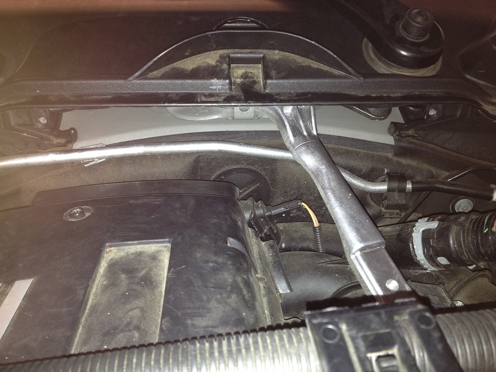
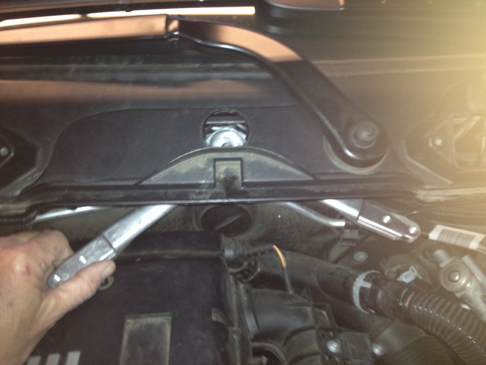
I removed the plastic aero tray under the front of the car - about 20 bolts - and unbolted the front E93 brace:
![Name: E93 Front Brace Unbolted [04 sm].jpg
Views: 44689
Size: 218.9 KB](https://www.e90post.com/forums/attachment.php?s=4f52d3fb1c0917873af446a78d080b5d&attachmentid=657680&d=1331652370)
Remove the front brace arms. Now the suspension can be accessed.
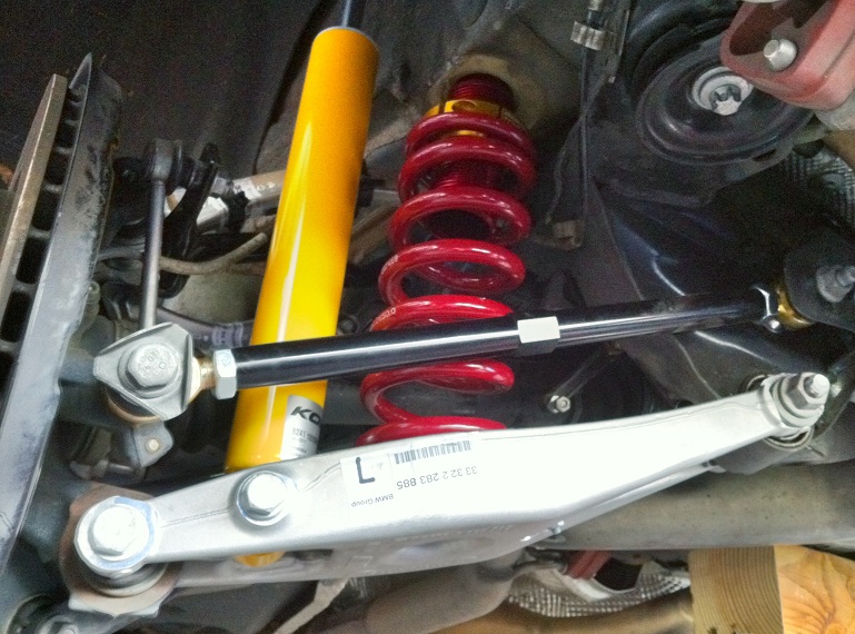
R&R FRONT WISHBONES AND TENSION STRUTS
Not much to this. Each arm is bolted at one end; needs nut removal at the other. Pull off. Replace w/M part.
Doing one side at a time, use impact wrench to remove bolts/nuts. R&R one arm before doing another - a wishbone and a tension strut for each side - view
stock arms #14 & #9 here and
M parts #14 & #19 here.
It's best to jack the knuckle up to normal ride height to remove/install, otherwise you'll find undue stress.
IMPORTANT: Suspension bolts should be started but not torqued until all bolts are in - give your suspension room to move so that all bolts can be fitted w/o stress - if necessary, loosen a few other bolts to achieve this. Otherwise you could cross thread a bolt!
IMPORTANT: Torque all suspension parts while at normal ride height with steering wheel centered. See Appendixes A & B.

Pic borrowed from
1fastBMW - thanks!
R&R FRONT SHOCKS/SPRINGS [STRUTS]
First, free wires and brake hose from the strut. Compress the springs - I used these Craftsman spring compressors:
![Name: 2012 01_10 - Driver hand tighten [sm].jpg
Views: 35975
Size: 291.9 KB](https://www.e90post.com/forums/attachment.php?s=4f52d3fb1c0917873af446a78d080b5d&attachmentid=657695&d=1331653233)
Jacked the knuckle up & hand tightened, the easy way to do it. When fully compressed, removed the nuts from the strut studs in the engine compartment and lowered the wheel....tilted strut out for removal....CAREFUL not to scratch fender wheel well paint! Some tape the wheel well - look back 2 pics to see.
![Name: 2012 01_10 - Driver strut out [sm].jpg
Views: 36258
Size: 283.8 KB](https://www.e90post.com/forums/attachment.php?s=4f52d3fb1c0917873af446a78d080b5d&attachmentid=657696&d=1331653233)
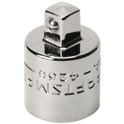
Now the pinch clamp must be widened. I used a 3/8 female x 1/4" male adaptor - 1/4" fits right in; turn 45 degrees. Strut lifts right out! Only good for a couple of tries - corners of the 1/4" end round easily - I went through 2 - they're inexpensive and I didn't want to wait to receive a
strut spreader tool.
Thanks, mike-y, for the tip and this pic!
[Post #2]
![Name: 2012 01_10 - Driver strut pinch bolt [sm].jpg
Views: 36624
Size: 241.7 KB](https://www.e90post.com/forums/attachment.php?s=4f52d3fb1c0917873af446a78d080b5d&attachmentid=657697&d=1331653233)
Reverse order to install new strut - there's a button on the strut that slots through the opening in the pinch clamp - you cannot put it in wrong. Careful to be sure wiring is returned to correct route.
Remember, engine compartment nuts will be torqued when car's back on the ground with the steering wheel centered. In my case, I tightened engine compartment strut mount nuts finger tight - still have strut brace to install using those studs.
I left the gold Ground Control height adjustment collar threaded all the way up until time for ride height adjustment.
![Name: GC Strut [03 sm].jpg
Views: 37242
Size: 262.2 KB](https://www.e90post.com/forums/attachment.php?s=4f52d3fb1c0917873af446a78d080b5d&attachmentid=657700&d=1331653874) R&R FRONT SWAY BAR
R&R FRONT SWAY BAR
The front sway's easily unbolted, end links & mounts; removed. Then, a problem: How to mount w/2 part
M3 sway bushings.
Stock here. My solution was to rubber mallet them into place - snap! Apply silicone grease to the bushing prior to install so they can easily rotate on the sway bar. Install new M sway in reverse order.
Move both hubs to normal ride height with steering wheel centered & torque all bolts & nuts. See Appendixes A & B.
![Name: Front Sway Bushing [03 sm].jpg
Views: 34826
Size: 215.0 KB](https://www.e90post.com/forums/attachment.php?s=4f52d3fb1c0917873af446a78d080b5d&attachmentid=657705&d=1331654147)
![Name: Front Sway Bushing [05 sm].jpg
Views: 34098
Size: 269.0 KB](https://www.e90post.com/forums/attachment.php?s=4f52d3fb1c0917873af446a78d080b5d&attachmentid=657706&d=1331654147)
![Name: Front Sway Mount Installed [1 sm].JPG
Views: 37343
Size: 291.7 KB](https://www.e90post.com/forums/attachment.php?s=4f52d3fb1c0917873af446a78d080b5d&attachmentid=657707&d=1331654147) R&R STRUT BRACE - ENGINE COMPARTMENT
R&R STRUT BRACE - ENGINE COMPARTMENT
Here's my procedure for the
M strut brace, a major pain!
I followed
this procedure, but was stumped when the center cast piece wouldn't go over the tab at all. No matter what. No way, no how.
Solved by slipping it in from the side, a tight fit! Perseverance carried the day.

Bolted it together loosely - until back on the ground w/steering wheel centered, front suspension properly torqued, maybe the last part of this job.
DROP THE REAR SUBFRAME BUT NOT THE EXHAUST
I dropped
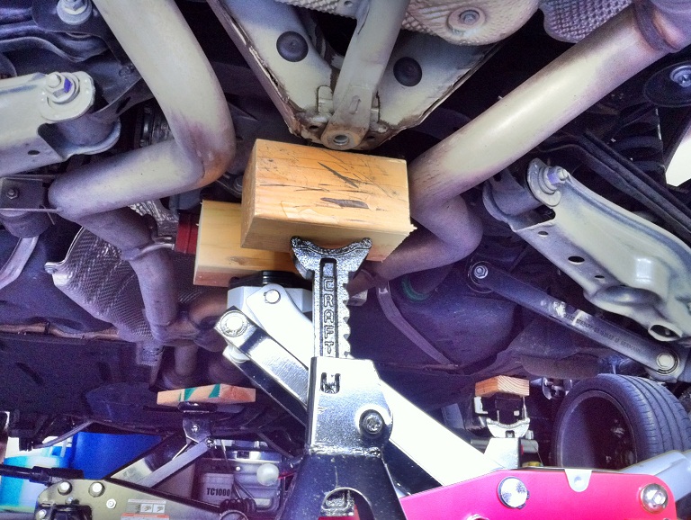
the rear subframe 3-4" to enable rear subframe bushing & sway R&R. Support the subframe with a floor jack under the differential, again being careful not to include the diff cover in the contact patch. I placed a jack stand with 4x4 wood piece under the subframe cross member just rear of the diff; just forward of the brace mount as shown, 3-4" below the cross member [the amount of drop I want].
Unclip all wires at the wheels to allow slack, then disconnect brakes lines here:
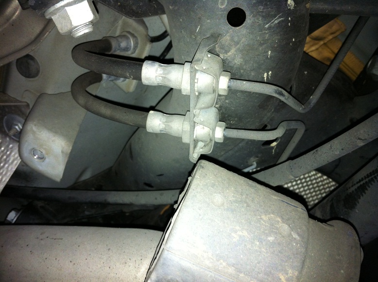
Use flexible line crimps or quickly plug the flex lines to prevent draining brake fluid to your floor. DO NOT allow brake fluid to contact your paint - it will permanently damage the finish! If it does go there, don't attempt to rub it off - dab up w/paper towel.
Next, rather than dropping the exhaust, I disconnected at the flanges forward of the cats, a 4 nut removal, easy:
![Name: Exhaust forward disconnect [75].jpg
Views: 33034
Size: 121.2 KB](https://www.e90post.com/forums/attachment.php?s=4f52d3fb1c0917873af446a78d080b5d&attachmentid=678357&d=1334889416)
Image borrowed from
jprandkpr
Also removed the reinforcement plate w/8 torx bolts:
![Name: Exhaust plate [75].jpg
Views: 33575
Size: 120.4 KB](https://www.e90post.com/forums/attachment.php?s=4f52d3fb1c0917873af446a78d080b5d&attachmentid=678358&d=1334889416)
Image borrowed from
jprandkpr
Then removed the mid pipe brace, one bolt:
![Name: Exhaust mid pipe brace [75].jpg
Views: 33085
Size: 144.4 KB](https://www.e90post.com/forums/attachment.php?s=4f52d3fb1c0917873af446a78d080b5d&attachmentid=678359&d=1334889416)
Image borrowed from
jprandkpr
That allowed my exhaust piping to move with the subframe drop; I supported the cats/silencers with a jack stand and section of 2x6 wood. Disconnected rubber hose operating the rear exhaust flap. When I later needed to drop one side or the other, I removed rearward hanger mounting bolts rather than muscling off the rubber hangers.
Had I dropped the exhaust, somewhat heavy, I'd of had one big matzoh there with nowhere to go! Totally in the way of my creeper, needs removal from the work area. Big pain. T'heck with that, I said.
I removed all 6 subframe bolts and g-e-n-t-l-y lowered the subframe onto my jack stand's 4x4 wood block [look 5 pics back; above].
R&R REAR SUBFRAME BUSHINGS
Next, I used
HP Autowerks' subframe bushing tool to replace all four
stock bushings w/
M subframe bushings. It's easy enough with an impact wrench, but DON'T forget to lube your threaded rod [used 20/50 motorcycle oil....no lube = seized nut!], and please, butter your bushings with silicone grease for a sa-mooth install.
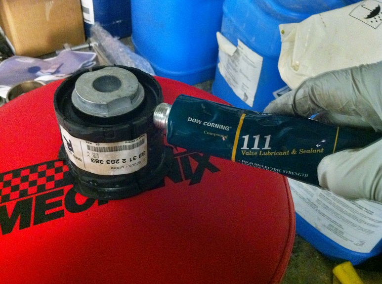
I bought the pictured Dow Corning 111 silicone grease at WW Grainger.
All stock bushings come out from the bottom, but front M bushings go in from the top; rear M bushings go in from the bottom. HP Autowerks' tool highly recommended - <$60 rental - makes the job very easy.
R&R REAR SWAY BAR
M Sway was reputed to be a difficult R&R but critical, as it is dramatically beefier than
the stock sway. I didn't find it hard at all, once I devised a way to snap the rear sway 2 part bushings together on the bar.
Simply drilled a couple of holes in bar stock - slowly tightened bolts by hand - snap! snap! The clips went right in on the bar. Use plenty of silicone grease on bushings so that they turn easily on the bar.
Do not use a rubber mallet! Rear sway bushing assy's are of very diff composition than front, and will explode like an evil jack-in-the-box if you try to mallet them together.
Scads of room to maneuver with subframe dropped 4" - a smooth install.
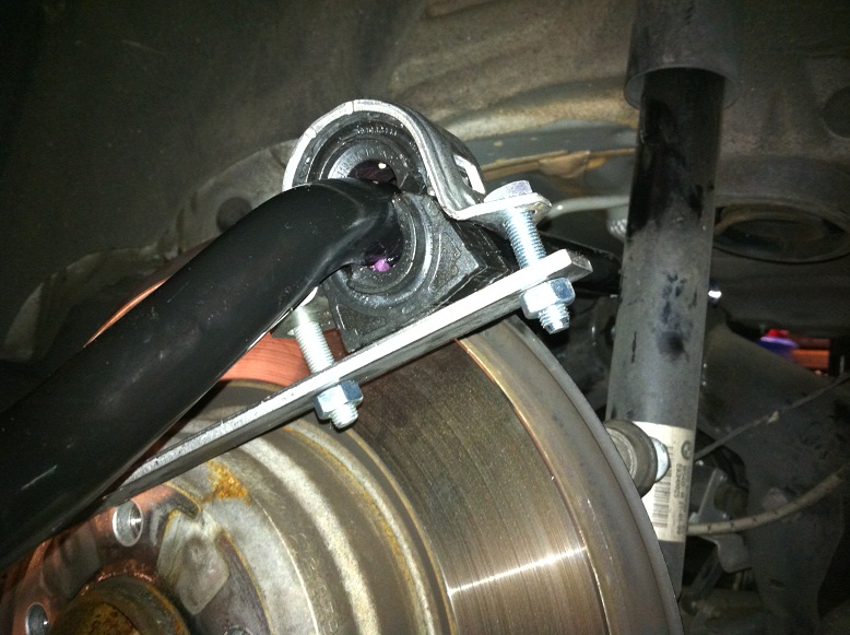
Torqued mount bolts but left end links disconnected as the much fatter M sway must be moved out of the way to R&R guide rod mount bolts at the bearing carrier.
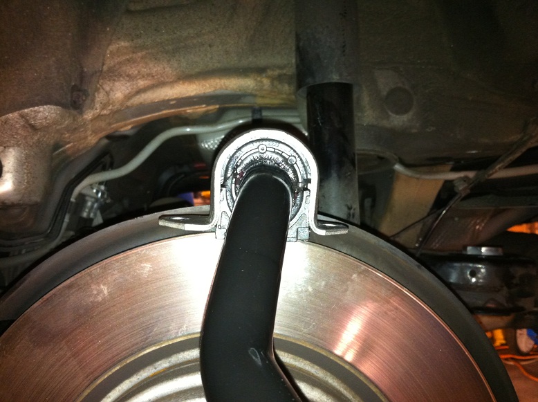
Raise subframe and torque the 6 subframe mount bolts.
IMPORTANT: Start all subframe mount bolts by hand,
then tighten all barely snug,
then tighten to torque value. If you tighten each bolt to torque before starting the next, you stand a good chance of having the last bolt or two not thread in, being offset a small ammt by new bushings. Save yourself some time and frustration - follow this procedure.
Remember to re-clip wires and reconnect brake lines.
IMPORTANT: Bleed your brakes!! [Post #30] If you get air way up in there,
activate the ABS pump.
R&R REAR WISHBONES AND GUIDE RODS
On to
M Suspension Arms [Parts #17 & #18].
Stock arms here.
Again, not much to this. I replaced the wishbone & guide rods.
IMPORTANT: At the rear especially, suspension bolts should be started but not torqued until all bolts are in - give your suspension room to move so that all bolts can be fitted w/o stress - if necessary, loosen a few other bolts to achieve this. Otherwise you could cross thread a bolt!
IMPORTANT: Doing one side at a time, move the wheel hub to normal ride height when removing/reinstalling bolts to avoid undue stress. See Appendixes A & B.
Move sway bar up to access guide rod bearing carrier mount bolt. R&R one arm at a time. When finished both sides, install M sway bar end links, both rear hubs at normal ride height; torque all bolts & nuts.
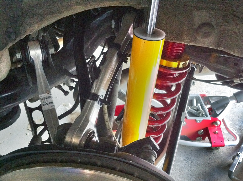
R&R REAR SPRINGS, SHOCKS, CAMBER ARMS; TOE ARMS
Again one side at a time, I then R&R'd shocks, springs, camber arms and toe arms.
IMPORTANT: The headlight leveling sensor is connected to the driver side rear camber arm with a rod. Disconnect before removing camber arm mount bolts or you WILL damage the sensor - think $60 and PITA trip to the parts counter. You may wish to replace the sensor with the M3 sensor to obtain the repositioned sensor arm, ready-made. Read about need for 180° change in sensor arm position on M3 camber arm install, 14 para's below.
IMPORTANT: The shocks prevent the wheels from articulating to the point of CV joint damage. When disconnecting this assy, support the bearing carrier with a jack stand. Handy point to do so just inboard of the disk, forward.
Unbolted shock & two mounting bolts; removed camber arm. Must drop exhaust some to get inboard bolt out. Dropped each side individually so did not have to drop the whole exhaust - remove hanger mount bolts/nuts on one side to accomplish this. Jack stand can be used to support freed side but I let it rest on my bod [on creeper] as I attached the camber arm; immediately reinstalled the exhaust. Then, did other side.
Springs fall right out. Spring hat pops off by tapping a bladed screwdriver in between hat & subframe. Only the top shock mounts left to unbolt and brother, that's when my troubles began!
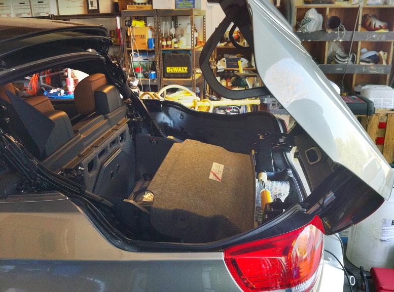
The trunk of an E93 is, put mildly, crowded. There're hundreds of lb of hydraulic gear and roof strut to deal with - following
this procedure, I attempted to remove side panels.
I swore. I screamed. I sat deep in thought....they wouldn't budge! Understand, they must be removed to R&R the shocks....all would be for naught without that.
I'l skip everything I tried; approaches were many. In the end I cut holes with my Dremel in the felted plastic panels above my struts to access the mounts.
That is not a trivial job in the trunk of an E93. Much is in the way....space cramped....Dremel a touch large....then it hit me: The E93 is uniquely suited to the job!
I raised the top part way, and all was revealed.
I cut a hole....

I discovered: WIRES!

Big danger there....do you see the abraded covering? Luckily, though I didn't know about them until after removing the cutout section, none were damaged. But forewarned is forearmed: be aware of this!

That done, assembly w/M camber arm wasn't a problem. Attach camber arm with inboard bolt; swing up to attach shock with bolt. Tap the Ground Control sping hat into position - O-ring will hold it there reasonably well. Use a floor jack w/bit of wood between camber arm & jack to move camber arm w/attached shock & installed spring up to position.
Careful to guide the spring so that the bottom part of the hat slides into the spring. Attach to bearing carrier with bolt. Leave Ground Control gold height adjustment collars (top of spring) threaded all the way up until ride height adj time, otherwise the rear suspension may not be able to reach normal ride height, preventing the upper control arm & guide arm bolts from threading in properly at the bearing carrier.
Now you'll find the connecting rod for the Headlight Vertical Aim Control Sensor does not reach from the M3 camber arm mount!
The problem is: Sensor arm needs to be rotated 180° to connect.
335i headlight level sensor parts, rear --
M3 headlight level sensor parts, rear Unless connected your headlights will freeze in a fixed position, most often pointing up, irritating oncoming drivers. Yow! The M3 mount is significantly outboard of the 335i mount:
![Name: Offset Arm [003] [30].jpg
Views: 39512
Size: 142.6 KB](https://www.e90post.com/forums/attachment.php?s=4f52d3fb1c0917873af446a78d080b5d&attachmentid=698653&d=1338317025)
New part? Check electrical operation? Rather than fool around, I went KISS: Fab'd a 1.5+" offset bracket from a small piece of Ace Hardware aluminum sheet stock:
![Name: Offset Arm [012] [30].jpg
Views: 32869
Size: 245.8 KB](https://www.e90post.com/forums/attachment.php?s=4f52d3fb1c0917873af446a78d080b5d&attachmentid=698654&d=1338317025)
I rolled the tabs around the M3 mount for a secure fit and bolted together - viola! New mounting hole approx. where the 335i camber arm provided it. Leveling system now works, maybe a quick headlight alignment needed, easily done. No new M3 sensor; no sensor arm rotation. Just good ol' shadetree ingenuity. Did I do good?
Back to installing suspension components:
IMPORTANT: Leave bolts started but not torqued to allow suspension movement until ALL bolts are in. Only then should suspension bolts be torqued down.
![Name: RR Suspension 01 [sm].jpg
Views: 34550
Size: 151.8 KB](https://www.e90post.com/forums/attachment.php?s=4f52d3fb1c0917873af446a78d080b5d&attachmentid=657742&d=1331657955)
Then,
toe arms -- maybe the easiest part -- zip, zip.
 FINISHING TOUCHES
End game: Meticulous double check to be sure all nuts & bolts have been correctly torqued with hubs in the normal drive position and steering wheel centered. You'll have found by this point that using a torque wrench is best done on a lift as exerting up to 122 ft lb torque w/ride on jack stands is not the easiest of tasks. Can be done, but you may struggle!
Reinstall E93 bracing, reinstall plastic front undercarriage aero sheet, torque engine compartment strut mount & strut brace bolts with all paws on the ground; do ride height adjustment.
IMPORTANT: After lowering your ride to pavement, start your engine and run your 3 couple of times back & forward a few feet to move wheels to normal drive position. Be sure your steering wheel's centered as you roll.
THEN torque strut bolts. Otherwise, you may stress strut mount bolts:
![Name: 2012 05_27 - Camber Plate Sheared Bolt [A] [30].jpg
Views: 32559
Size: 165.4 KB](https://www.e90post.com/forums/attachment.php?s=4f52d3fb1c0917873af446a78d080b5d&attachmentid=698666&d=1338317685)
![Name: 2012 05_27 - Camber Plate Sheared Bolt [C] [30].jpg
Views: 32645
Size: 176.3 KB](https://www.e90post.com/forums/attachment.php?s=4f52d3fb1c0917873af446a78d080b5d&attachmentid=698667&d=1338317685)
I ground off the tack weld on the broken bolt; threaded in new and installed it correctly. Expecting no further trouble.
Ground Control provides for ride height adjustment -- see the gold rings on struts & spring hats
[click here]? They're threaded on the red cyl to provide that adjustment. Sweet! Again, I had screwed all stops to the top of the adj cylinders before final height adjustment to allow knuckle (front) & bearing carrier (rear) movement to normal ride height while R&R'g parts.
GOLF TEE MOD
One last little thing. re: N54 -- If you crimp the rubber vacuum line to disable the driver's side exhaust flap at the rear of the car, you'll change low rpm behavior in a very pleasing way - much better modulation & torque. I did it with a plastic wire tie. Exhaust also louder, not a big plus for me as the sound isn't quite what I like, but good feedback. Known as the "Golf Tee Mod." Easily Googled - you'll find many DIY docs & YouTubes.
__________________________________________________ _
UPDATE: Uncrimped my rubber vacuum line. Found reduced back pressure resulted in lower low rpm torque which, though it seemed to enhance low rpm throttle control, yielded lower low rpm thrust and ran a touch rougher. Restoring to stock was a return to smoothness and torque, so much so that I'm skipping this mod unless/until new engine settings are figured out, maybe adj'd with JB4.
Done! Off to the alignment shop....an OUTSTANDING experience I recommend to everyone.

-------------------------------------------------------------------------------------
TOE ARM UPDATE
10 months later, clicking at my rear suspension; suspect worn toe arm Heim joints.
When cool weather's here, no click....yet. Looking into
Megan toe arms - more later!

-------------------------------------------------------------------------------------
Appendix A - Wheel normal ride height
Ride height is measured from the top of the wheel well fender flange to the bottom of the wheel rim.
Front Stock Values:
16" wheel -- 22.99 in -- 584 mm
17" wheel -- 23.58 in -- 599 mm
18" wheel -- 24.09 in -- 612 mm
19" wheel -- 24.60 in -- 625 mm
Rear Stock Values:
16" wheel -- 22.24 in -- 565 mm
17" wheel -- 22.83 in -- 580 mm
18" wheel -- 23.35 in -- 593 mm
19" wheel -- 23.82 in -- 605 mm
But if you wish to work with wheels off the car, which I did, measure from the top of the wheel well fender flange to the bottom of the hub. That was 18.7" front; 18" rear on my car.
Front wheel hubs I raised to normal ride height with floor jack and a piece of 2" x 6" wood under the hub as shown in pic #5 from the beginning of this post.
Rear hubs I raised with floor jack & short length of 4" x 4" wood under the camber arm just inboard of the bearing carrier.
IMPORTANT: Ground Control suspension intended to reduce ride height maybe an inch. I did 3/4".
Appendix B - Torque Values
____________________________________ Ft Lb ________ N/M
WHEELS
Wheel Lug Nuts..........................89..........120
EXHAUST
Exhaust - forward flanges...............15...........21 - turbo
........................................33...........45 - non turbo
Exhaust - reinforcement plate...........43.5.........59 - Torque +90° [-+30°] -- 8 Torx Bolts
Exhaust - mid-pipe brace................15...........20
Exhaust - hangers - differential........26...........35 - turbo
........................................22...........30 - non turbo
Exhaust - hangers - wheel carrier.......15...........21
Exhaust - hangers - rear chassis........15...........20
M3 STRUT BRACE
Bulkhead mounting bolt...............73.75..........100
All other bolts......................25.07...........34
FRONT SUSPENSION
Sway bar end link.......................44...........60
Sway bar mount to subframe..............16...........21....M8 bolts
Tension Strut @ knuckle................122..........165
Tension Strut @ subframe................74..........100
Control Arm @ knuckle..................122..........165
Control Arm @ subframe..................74..........100
Strut Pinch Clamp.......................60...........81
REAR SUSPENSION
Brake line to hose.......................9...........12
Sway bar end link.......................42.7.........58
Sway bar mount to subframe..............16...........21 - M8 bolts
Rear subframe bushings..................73.7........100
Upper Control Arm @ bearing carrier.....73.7........100 - Torque +90°
Upper Control Arm @ subframe............73.7........100
Guide Arm @ bearing carrier.............73.7........100 - Torque +90°
Guide Arm @ subframe....................73.7........100
Camber Arm @ bearing carrier...........121.6........165
Camber Arm @ subframe..................121.6........165
Camber Arm Shock Mount..................75..........102
Upper Shock Mount.......................27...........19.9 - M10
Upper Shock Mount.......................37...........27.3 - M14
Toe link @ bearing carrier..............73.7........100
Toe link @ subframe.....................73.7........100
-------------------------------------------------------
Disclaimer: I make no representation regarding the accuracy or advisability of any value or procedure in this post - this is what I did for my ride. Yours may be different! Other models may require other procedures and data - verify everything as for your vehicle before you do any of what I've done - you proceed at your own risk.