... continuing from previous :
- Next on the list was to free steering knuckle from the thrust arm, or a.k.a tension strut. Or a.k.a front upper control arm due to having its ball joints oriented from top to down on the steering knuckle. workshop-manuals.com, which seems to be using some copy of BMW workshop manual, calls these "compression strut"s for the X-drive (AWD) versions. I guess it is about it is orientation. On the RWD models, this arm is connected to the frame of the car in front of the wheel. On X-drive (AWD) versions it is connected to the frame behind the wheel. In first case it is in
tension when car moves forward, in the later it is in
compression when the car moves forward. I had removed these not so long ago to replace the bushings on the other end of these compression struts, and had used anti-seize on the ball joint studs. So this time I opted to disconnect these arms from the ball joints. My reasoning was, it would be easier to handle the steering knuckle with the axle to remove and put back without the additional weight of this arm hanging from it. Also I wouldnt have to bother compressing the strut coil to bring it to ride height before tightening the bushing bolt on the frame side of this arm if I had to remove it from the frame. Also the bolt on the bushing side is one time use ideally, it is torqued to yield during tightening. If I had too much trouble freeing from its ball joint due to rust I would chose disconnecting it from the frame at the other side where the bushing is. With the anti-seize used last time, these just dropped off without any need to use hammer on them. The first time I had removed them for bushing replacement, I had used a lot of penetrating oil, plus a lot of hammering on the arm where the ball joint stud goes through, and also applied downward force with a pry bar leveraging from the knuckle while hammering, which eventually had worked to pop off. Patience, persistence, penetrating oil, repeated impacts and heat works to free rusted parts. Patience and repeated impacts being the most crucial in my experience.
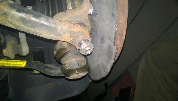
- Also this ball joint pictured above has a torx hole to prevent it from turning during loosening and tightening, works well with the 24 mm box wrench. Initial loosening I used the ½ inch air impact wrench again, which is the best tool for that job.
- Next I removed the allen bolt that holds down the abs sensor to the steering knuckle. The bolt came out easily, but not the sensor. Even though the sensor is plastic, it was frozen in place due to rust build up around its hole and swelling up and tightening it. Used penetrating oil on it, and careful prying with a thin screw driver it came out fine. It could have been broken if I wasnt careful, it is old plastic, becomes fragile. Bentley manual says to put some special grease on it before assembly, and seeing all that rust how froze it this made sense. Not having that whatever special grease BMW says to use, I used silicon grease that I had used on the brake pads when I put them back during assembly.
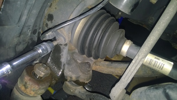
- Next I removed the bolt that connects the wishbone, a.k.a front lower control arm due to its ball joint oriented from down to up on the steering knuckle, or just control arm as workshop-manuals.com BMW manual calls it. It is the straight control arm, not the curved one. I didnt attempt to disconnect this from the ball joint end on the steering knuckle because the nut of that ball joint is blocked by the CV axle. Maybe a thin walled box wrench could fit there, but with the years of rust I doubt it would be enough to free it. So saved the trouble and disconnected the bolt and nut on the frame side of this arm. This bolt is also torqued to yield, but I had already bought new bolt and nut. An 18 mm box wrench comes handy here along with a socket on the other side.

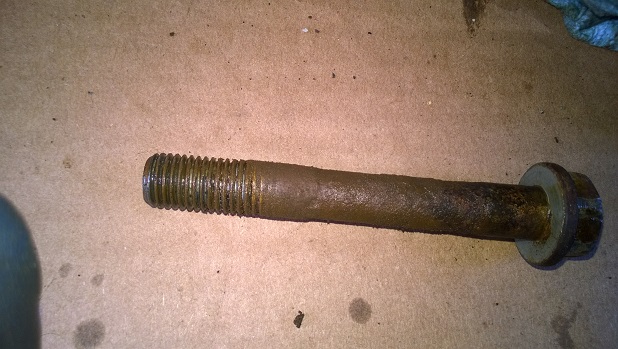
- The nut on this bolt came out fine, and the bolt on the driver side also came off after small tapping on it with a hammer. But the one on passenger side was not coming off. I put the nut back on the bolt so that it was flush with the bolts end, so that it would prevent the bolt from mushrooming from hammer hits, and started hitting heavily with big hammer, it wasnt moving. Again after patience, persistence, multiple applications of penetrating oil, and hammer hits it finally started to move and then hitting it back and forth from either end with more penetrating oil applied the bolt finally came out. It was not only rusted to the inside of the bushing, but also the part of the bolt that was right after the bushing ends had swollen big rust developed on it. This diameter increase of the bolt due to rust was very effectively blocking it to move out of the bushing. I was glad to have bought new bolts to replace these, next time it would be easier to remove. Pictures of the bolt and the bushing inside with rust turned into paste finally with penetrating oil and hammering:

- At this point the steering knuckle is supported by the strut/shock assembly, and still connected by the axle. My next step was to pop off the half axles, a.k.a CV axles from the differential. On drivers side, the axles goes directly into the front differential. On the passenger side, it goes into a pedestal that is bolted on the side of the engine oil pan first. From there it goes through a tube inside the engine oil pan and then to the differential. Differential itself is bolted to the engine oil pan. Differential oil exist inside this tube going across the engine oil pan.
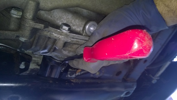
- First placed a drain pan where the axle goes into differential (or pedestal) to catch any differential oil that will likely to come off the axle seals during disassembly.
- The CV axles are held in place on the differential by c-springs. The ends of the axles are splined that spline into the side gears of the differential. The side gears have a grove cut into them. The axle spline ends also have a grove cut into them, but a c-spring is placed into this grove. When assembled this c-spring goes into the grove on the gear on the differential preventing it to come off. Because it is a spring, if compressed it gives way and lets the axle come out. This is done by sharply prying off the axle CV joint at the differential side by placing a pry bar between the CV joint and the differential body (or the pedestal on the passenger side). For the BMW I hadnt luck with prying it off with sharp prying hits like that. So I placed the pry bar against the body of the CV joint housing, and hit the handle of the pry bar with a hammer and driving the axle out. After a few taps with hammer, it popped off. Sometimes rotating the axle 90 degrees and trying again works. The idea here is to just pop it off, not drive it all the way out. If it came out more than 1/2 inch, it means it did pop off. I can tell from the change in resistance when it does pop off.
- Before doing this I examined the position of the CV axle differential end to the differential, how flush it sits and how much end play it has. The c-spring allows maybe 1/8 inch or so play back and forth. I made a mental note of these so that during reassembly I would be able to tell better if axle had popped in good or not. On both sides when pushed towards differential the axle was very much sitting flush.
Below picture shows how I positioned the pry bar to tap at its end with a hammer to pop off free the axle from differential:
- Then next thing left was disconnecting the strut/shock assembly from the steering knuckle. First I marked the position of the shock to the steering knuckle with a marker, gold or silver one preferable, and preferably paint based marker. This is because there are two spot welded tiny dots for the lack of a better word on the shocks that go into the channel on the steering knuckle which provide alignment of the shock with respect to the knuckle. These spot welded tiny dots break off very easily, even when new. Even if one of these are left, it still provides alignment, but if both of them brakes there is nothing left to provide alignment of the shock to the knuckle. Placing marking on the knuckle and shock before disassembly would work for this purpose in case these break off during disassembly or assembly. Also the shock decreases in diameter towards its end, and the place where shock goes in the knuckle also has a corresponding taper for it. This prevents the shock to go through the knuckle all the way in case the pinch bolt gets loosened during usage of the car. It is not very easy to at least for me to align the taper of the shock tube to the taper of the knuckle clasp there. By marking the position before disassembly (assuming previous assembly had got it right) it removes guess work there for reassembly.
- Next I supported the steering knuckle under by a block of wood I had whose height happened to be just right. Otherwise I would have used a small floor jack, or the scissors jack I had with a block of wood to support the knuckle from under. I placed it right under the wishbone ball joint for support. Then unbolted the pinch bolt and its nut on the shock/strut assembly that was securing it to the steering knuckle. This bolt and its nut, just as the other bolt and nuts (except the ball joint nuts which are 24 mm) were 18 mm. An 18 mm deep socket worked better here due the length of the not allowing my regular 18 mm socket to seat on all the way.
- My experience from changing the shocks on the car before had taught me not to leave the pinch bolt there once it is loosened. Because the bolt goes in between though two spot welded dots on the shock tube. If the steering knuckle is bumped up or down while the bolt is in there but loose, bolt hits these dots and breaks them off.
- At this point, I started to lower steering knuckle to free it from the shock/strut assembly. I didnt have to but it could be needed to spread the knuckle clasp with a big screw driver or chisel, and use penetrating oil there to free it. I had replaced the shocks last year also, disassembly there wasnt difficult.
- As lowering the knuckle and freeing from the shock, I was at the same time I carefully pulling the CV axle out of its place too. The spline part of the axles, especially the c-spring on it, can damage the axle seal lips if not being careful during removal. They can even cause the tiny round spring that goes inside the lip of the axle seal get removed and drop there behind the seal. I had bought new axle seals anyway, and were going to replace these seals. Again, the differential being that expensive, and the work being so costly or time consuming and the seals being already old, being disturbed during this job, it didnt make any sense to try to save money on new seals. In any case when I removed the old seals later on, I made sure their round springs where on them, not had fallen down to the differential anywhere.
- So I removed the steering knuckles with the CV axles attached to them, being careful to keep the parts of the axles that go into the differential clean. I tried to be careful not to introduce any dirt or small rocks that into the differential during the whole job. Any small rock that would end up in the differential could easily destroy the bearings in there by time.
After doing the disassembly on both sides and removing the steering knuckles along with the CV axles, suspension part of the disassembly was done. Next was starting to drop the subframe, which continues on the next post...