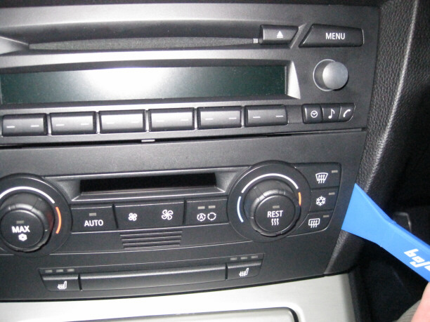
First remove the heater controls by prying out the left and right sides.
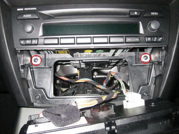
Then remove the two screws retaining the radio.
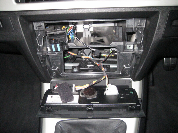
Pull the radio outwards. Disconnect the multi-plug, on the left, by releasing the plastic retaining lever upwards. Remove the connector for the aerial cable, on the right, by pressing the small tab and then carefully pulling the connector from the back of the radio.
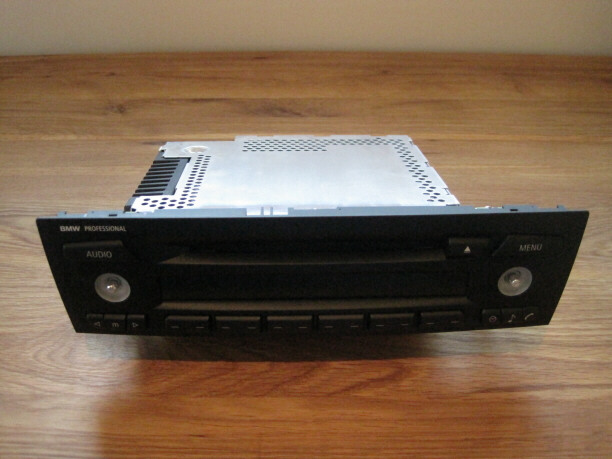
Remove the two buttons on the front panel of the radio, by pulling them firmly away from the unit.
Remove the lid by unfastening the screw indicated.

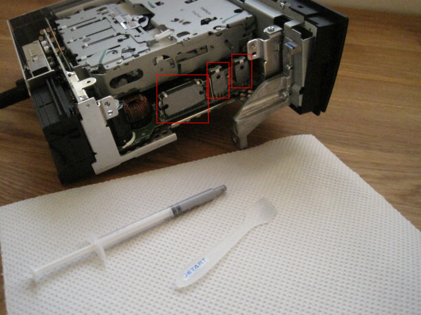
Remove the five screws on the left hand-side. Carefully pull the heat sink away.

There will be white thermal paste on the heat sink and the three chips. This should be removed using alcohol or citrus based thermal paste remover. It is best to remove most of the paste with a cloth and remove any remaining paste with a fine brush, dipped in the solvent. The radio should now look something like this.

Now remove the five screws securing the front panel.

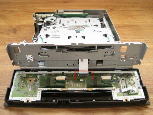
Tilt the top of the front panel away from the body of the radio. There is a plastic hinged flap on the connector indicated. Open this flap then disconnect the ribbon cable by carefully pulling the cable out of the connector.
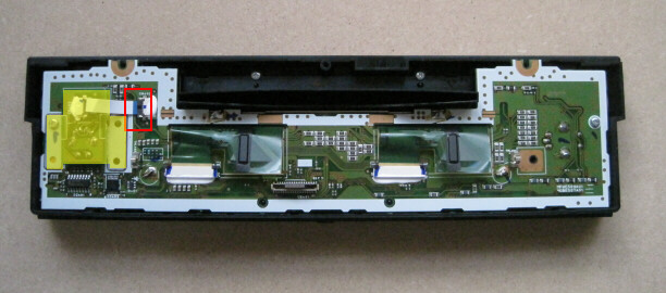
Carefully disconnect the ribbon cable to the right-hand control knob indicated. Remove the small circuit board (highlighted yellow) from the main circuit board.
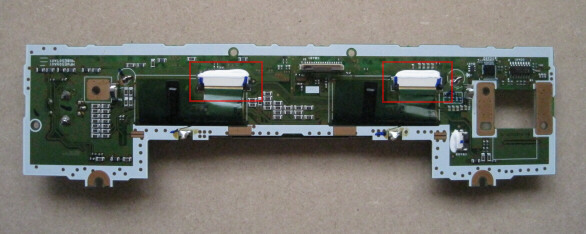
The LCD is connected to the main circuit board by two ribbon cables. These are very delicate and must be removed carefully, to ensure that they are not damaged.
Cut two small rectangular pieces of plastic from an old credit card, or similar, and place underneath the ribbon cables as they enter the connectors.

Using a clean finger, press gently downwards on the ribbon cable against the plastic underneath and pull the ribbon cable out of the connector.
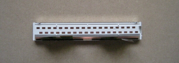
The LCD is housed in a metal frame which is fixed to the main circuit board by tabs, which are soldered at the points indicated. Unsolder these tabs, using a soldering iron and solder removal tool. Then straighten the tabs, using pliers, and remove the LCD assembly from the circuit board.


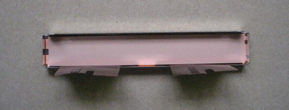
Remove the old LCD from the metal frame. Obtain a replacement LCD, type OPTREX 3231867, for your CD73 head unit. These are available on the internet, e.g. pixelfix.
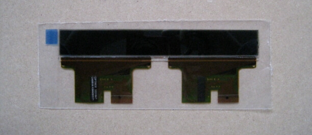
Carefully peel back the plastic film which is applied to both sides of the LCD. Then install the LCD in the metal frame and replace the plastic backing pieces.
Reassemble the radio in the reverse order. Take extreme care when reconnecting the ribbon cables as they are particularly delicate.
Remember to apply a thin layer of thermal paste to the chips before reattaching the heat-sink.
Finally, refit the stereo and check that it operates correctly. There is a test mode on the CD73 unit. Turn on the radio, then press and hold the ‘m’ button for approximately ten seconds. The test mode is navigated using ‘+’ and ‘-’, until it displays a number of test patterns. Exit the test mode by turning the radio off.
