Disclaimer:
This DIY uses wire twisting and electrical tape to join wires. My vehicle has no problems and works well, but you may want to consider other methods of wire joining:
http://www.mmxpress.com/technical/connections.htm
---
Background
No need to buy expensive harness like the
BMS Kit or the
Motive Mods Kit!
Build your OWN harness for half the cost using 100% OEM Parts!! No need to puchase new Multi-Function Button ("MFB"). BMS says you need it. Nope!
ENJOY!
Table of Contents- Preparation
- Assemble Pins - Paddles to MFB
- Assemble Harness - Slipring to Shifter
- Installation Part 1 - Paddles to MFB
- Installation Part 2 - Slipring to Shifter
- Installed Videos
Preparation
information compiled and edited by AoshichanX
taken liberally from
hugus311; miropm69;
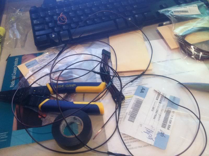
Tools Needed- 10mm Wrench/socket to disconnect the battery (Included in the OEM BMW tool kit above the battery)
- Large flat head screwdriver (prying the center console up, steering column cover removal)
- Medium flat head screwdriver (removing the airbag)
- 16mm socket with extension (steering wheel removal)
- Wire coat hanger or equivalent to pull the harness through the dash
- T20 & T30 torx tools (steering wheel parts)
- Crimper - Amazon (to strip wires; crimp)
- Ring Tongues - RadioShack (for ground connection behind airbag)
- Electrical Tape (insulate connected wires)
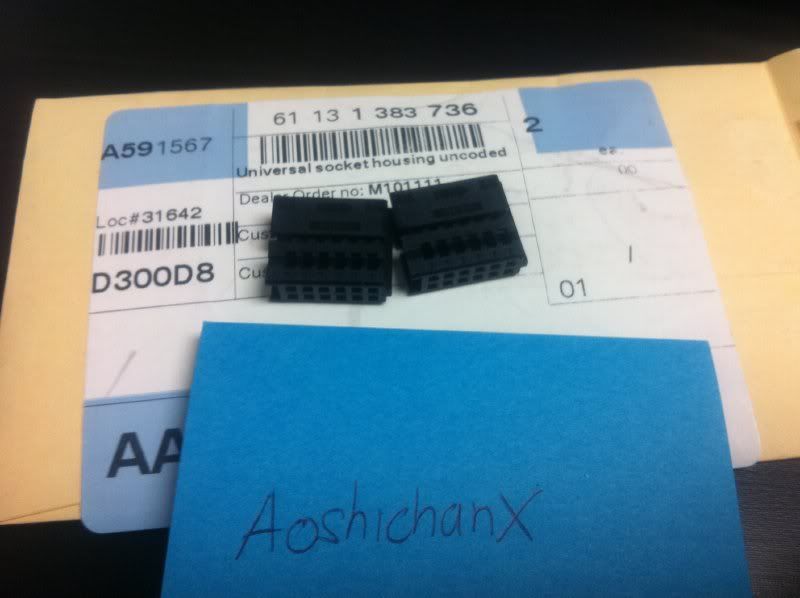
OEM Parts Needed for PNP- 2x connector housing socket (12 contacts) 61 13 1 383 736
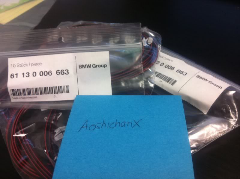
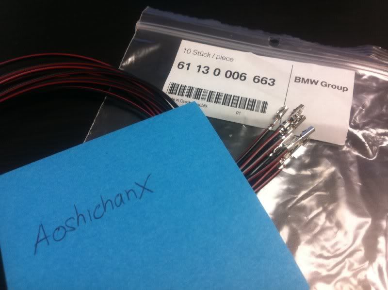
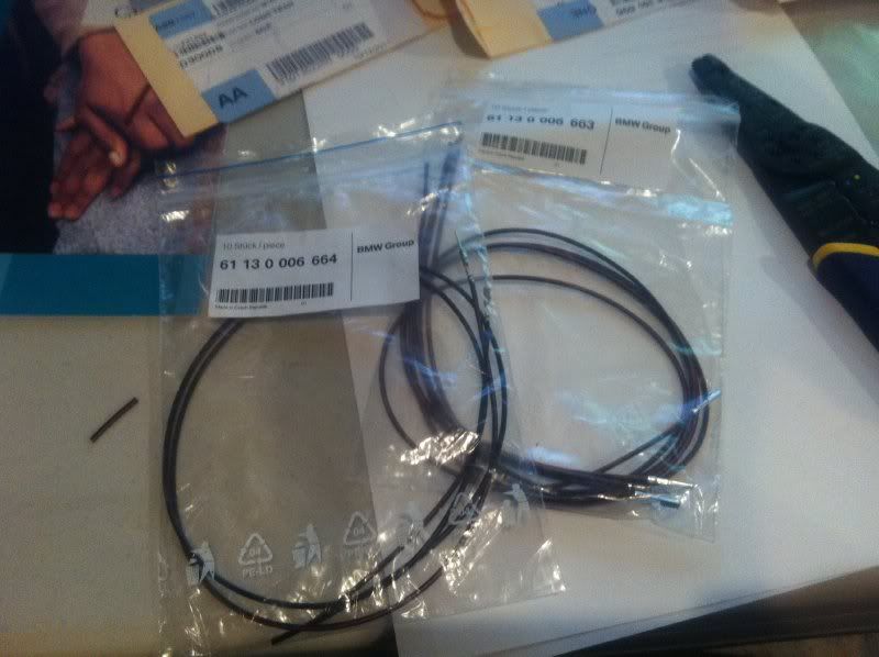
- 18x bushing contacts (female) 61 13 0 006 663
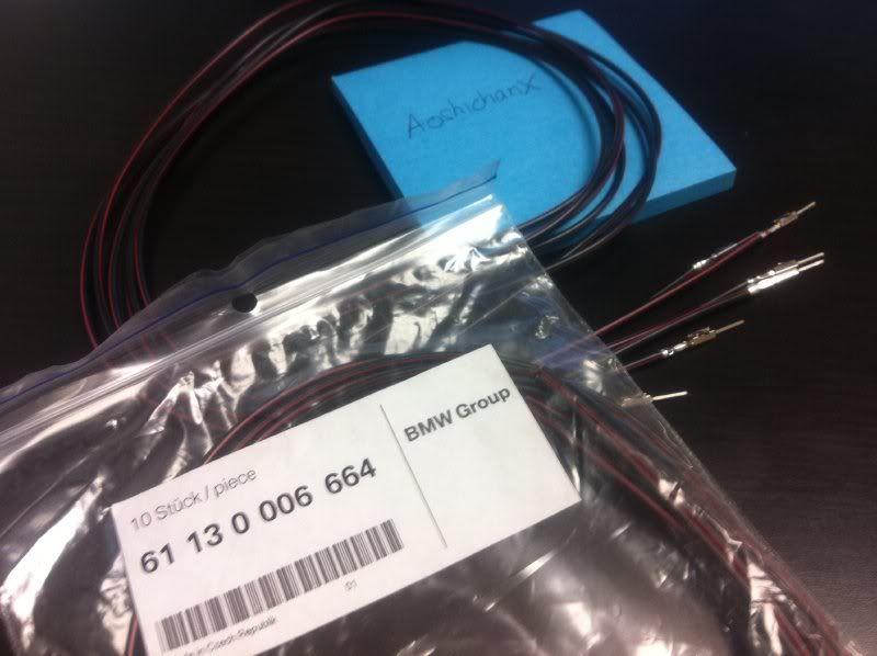
- 18x (for M3 DCT) OR 20x (for regular paddles) pin contacts (male) 61 13 0 006 664
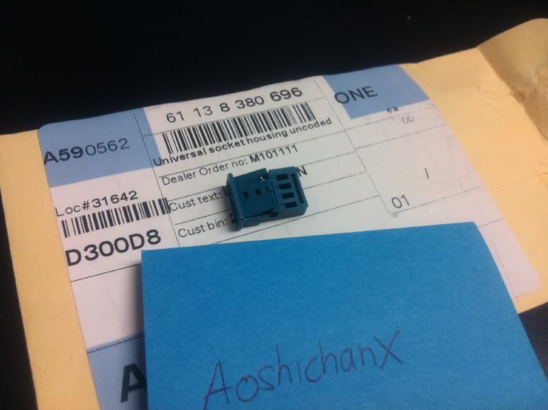
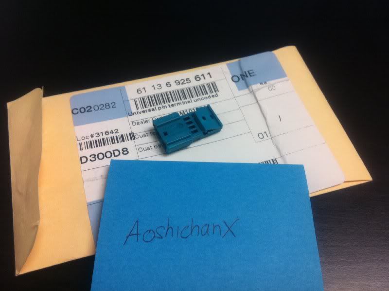
- 1x connector housing socket (4 contacts) 61 13 8 380 696
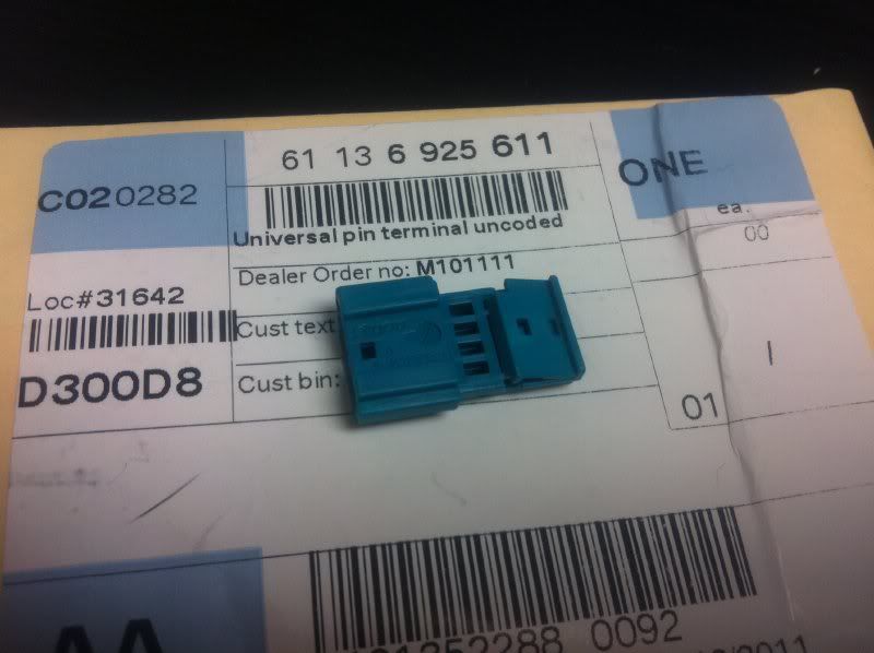
- 1x connector housing socket (4 contacts) 61 13 6 925 611
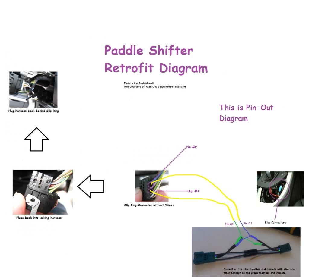
OEM Parts Needed for Pin-Out- 8x bushing contacts (female) 61 13 0 006 663
- 8x OR 10x pin contacts (male) 61 13 0 006 664
- 1x connector housing socket (short) (4 contacts) 61 13 8 380 696
- 1x connector housing socket (long) (4 contacts) 61 13 6 925 611
Guide- Make 14 short cables with a male contact on one and a female contact on the other end.
- Take the 12 contact housing sockets and insert contact by contact until each clicks in place One connector takes the female contacts, the other one the male contacts.
- Note: it is very important to not insert any cables in the housing contacts 2 & 4 (of the connector with the female contacts) and 8 & 10 (of the side with the male contacts). Let these empty!
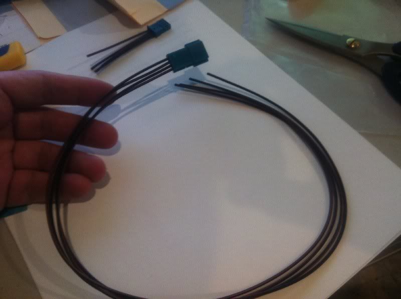
- Make two 40 (1m) long cables and crimp a female contact on one end. Insert it in the free slots 2 & 4 of your 12 contacts connector. (Contacts 8 & 10 over the other side will remain empty).
- You`ll have 4 short cables with contacts on remaining. Connect each of the long cables made to one of the short cables. Then insert the side with the male connectors in the (long) housing socket 61 13 6 925 611 and the one with the female in the short housing socket. The short cable connected to the long one that routes to pin 4 of the 12 contact connector goes into slot 3 and the one to pin 2 goes into slot 2.
- Always disconnect the battery ground terminal and reconnect it only after you`re completely finished or your airbag warning light will be on and you´ll need to get the error memory deleted.
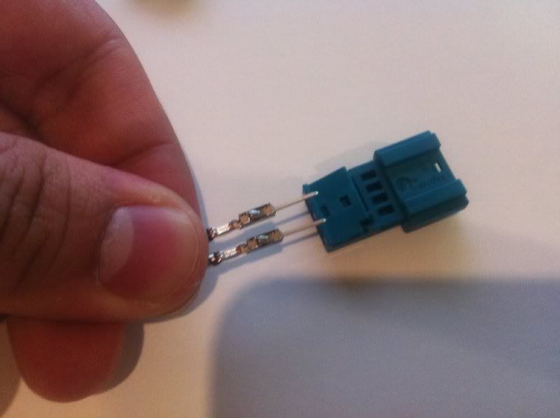
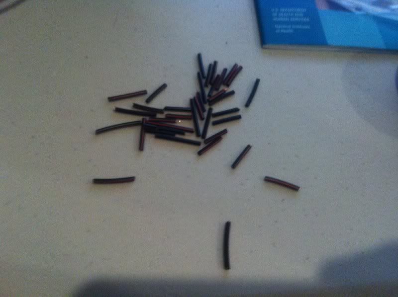
Ok let's begin by going over the parts. Below are the Male Pin Connectors. You need 18 of these for the M3 DCT Paddle Shifters. You will need 20 for regular/LCI paddles.
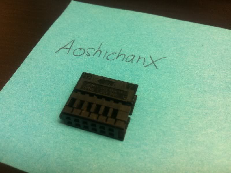
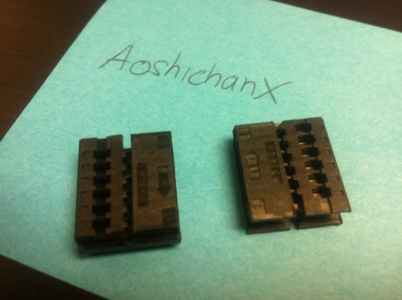
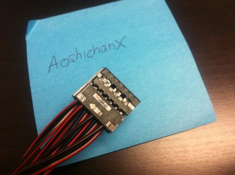
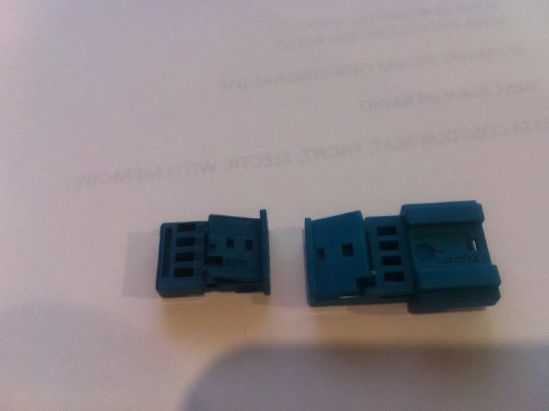
Here are the two 12-contact socket housing connectors you need.
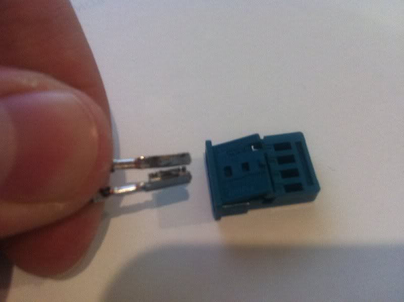
Shifter socket housing (long).
Shifter socket housing (short).
Shifter socket housing (long) - again.
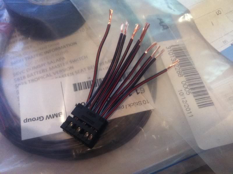
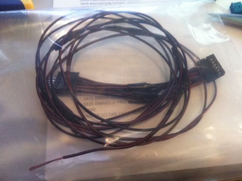
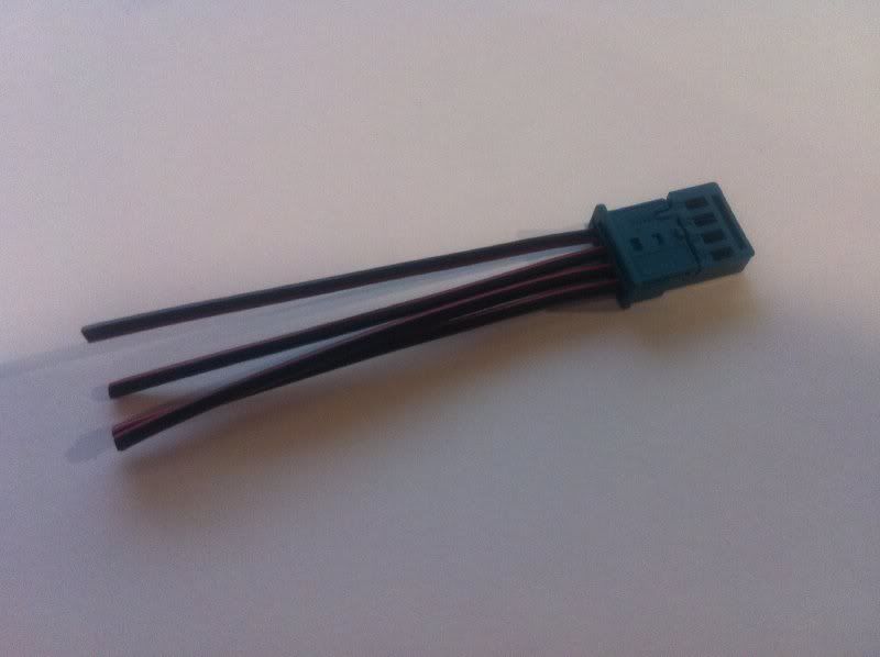
The pin connectors come with wires preattached. Score!
Female pin connectors. You will need 17 of these for M3 DCT. 19 if regular.
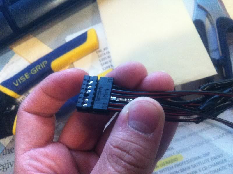
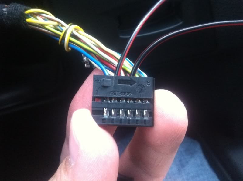
Close-up of the 12-contact housing. You can see numbers 1-6.
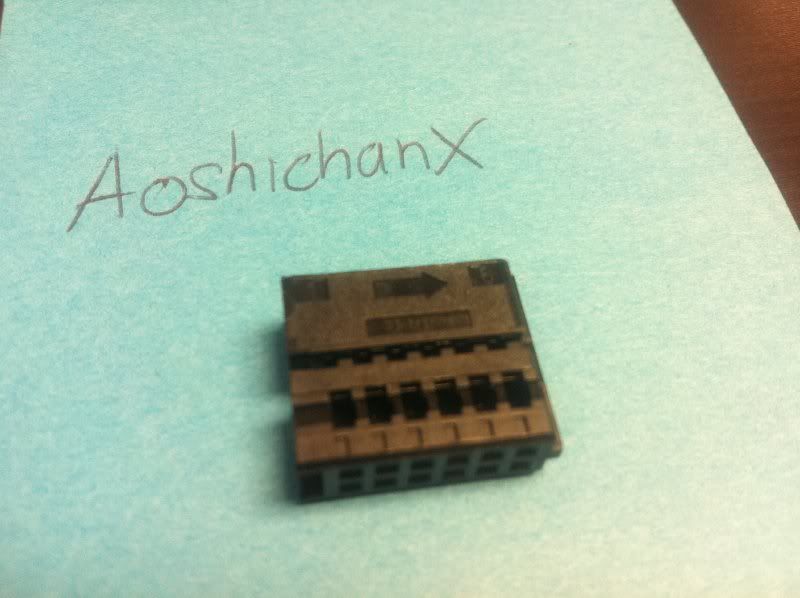
...and the other side is 7-12
 Assemble Pins - Paddles to MFB
NOTE:
I miscalculated the type of pins needed. You will not have this problem.
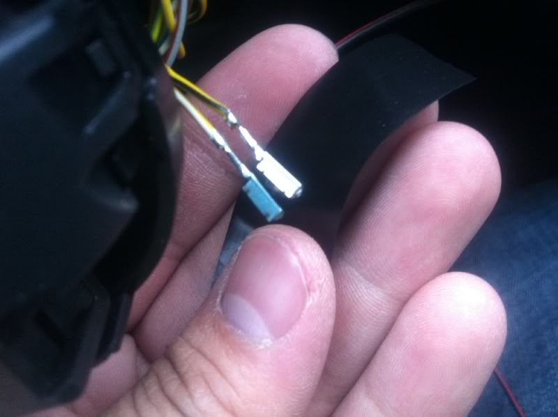
Lay out 4 Male Pin Connectors and 2 Female Connectors
Shorten Female Pin Connectors and strip. Strip to Male Pin Connectors.
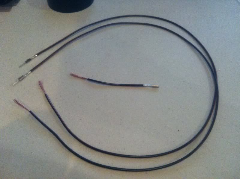
Make 2 male to female wires.
[NO PICTURE]
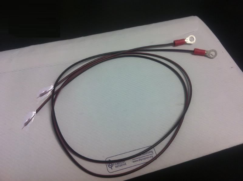
Lay out 2 Ring Tongues.
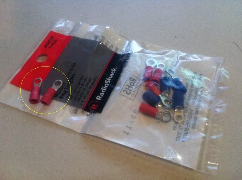
Lay out 2 Male Pin Connectors. Note: I ran out of Male Pin Connectors so I just got two spare wires.
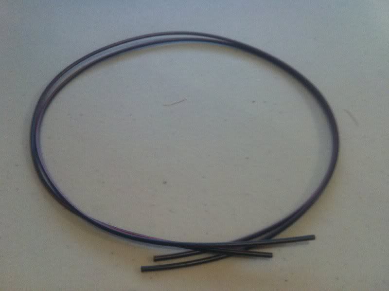
Strip the 2 Male Pin Connectors. Note: I ran out of Male Pin Connectors so I just got two spare wires.
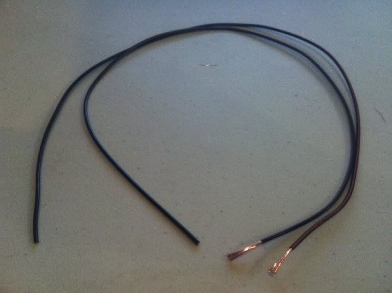
Thread wire through Crimp-On Ring Tongue
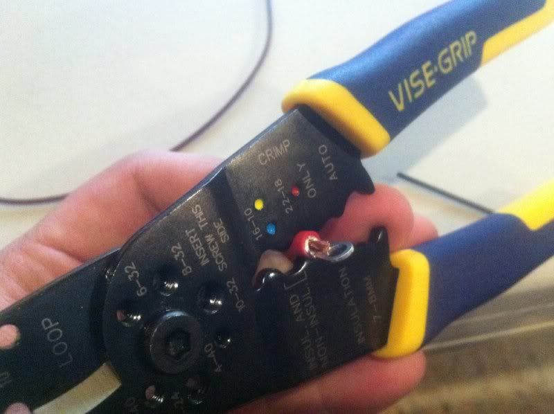
Crimp both wires. Note: I ran out of Male Pin Connectors so I just got two spare wires.
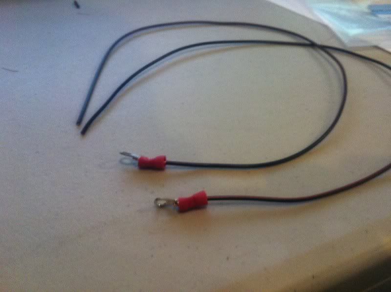
Now you have two Ground Wires. Note: I didn't have Photoshop on my work computer so I used Paint to copy over the male pin connectors. This is how it should look.
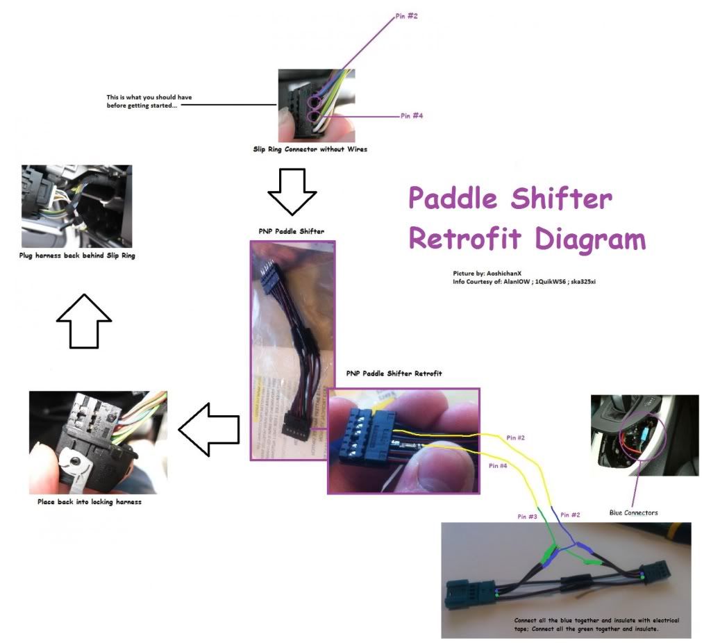
 Assemble PNP Harness - Slipring to Shifter
this is how it will look...imagine invisible wires in between.
Start plugging in the female pins one by one. Leave #2 and #4 empty.
Start plugging in the female pins one by one. Leave #2 and #4 empty.
Leave #2 and #4 empty.
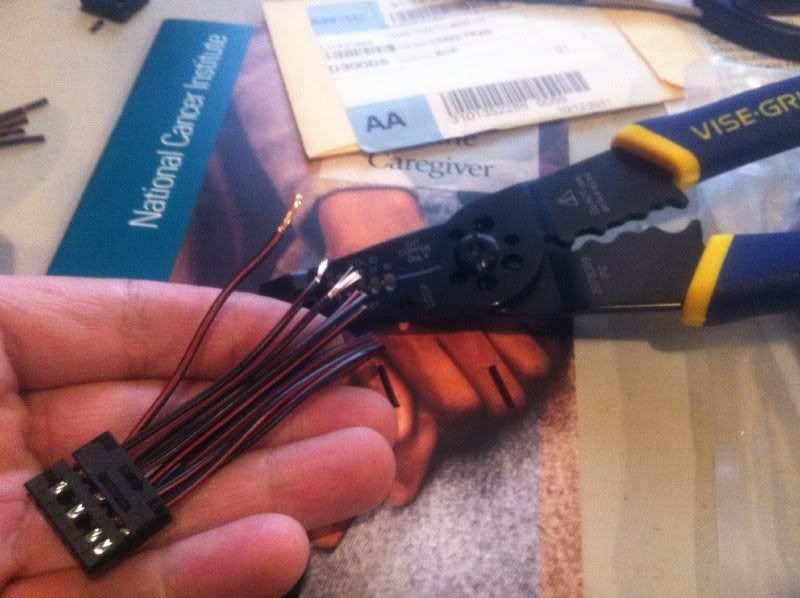
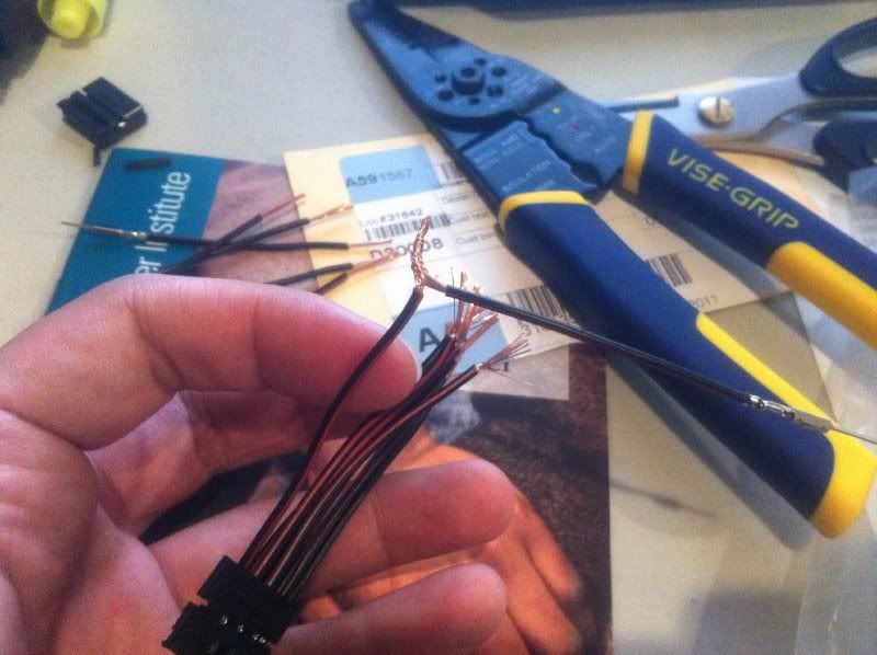
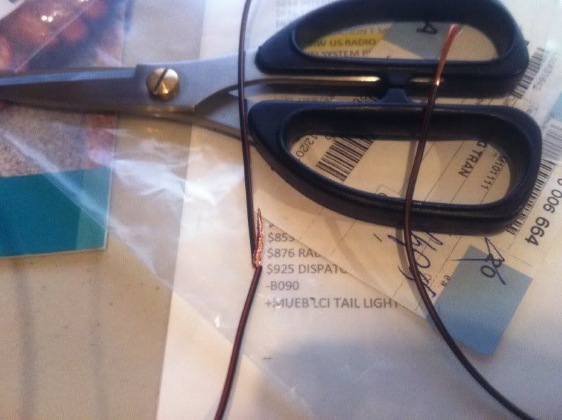
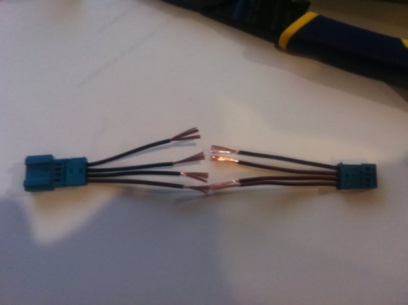
The wires are too long, cut them. Then strip some wire with crimping tool. I bought the Irwin Industrial one from Amazon for $12.80 shipped.
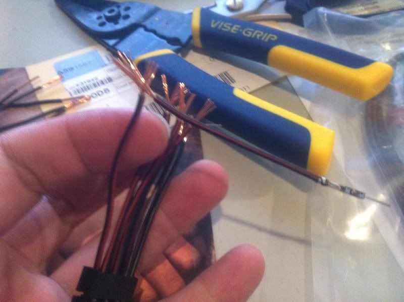
Ok! All Stripped!
Do the same for the male connectors.
Now spread the wire like a fan and join with female like this:
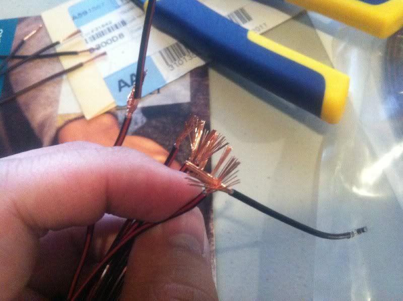
Then twist like this:
Insulate with electrical tape:

Once all joined, plug the male pins in the other 12-contact connector.
Remember to leave pins #8 and #10 empty.
On the female side, plug an uncut female pin to pins #2 and #4.
Now it looks like this.
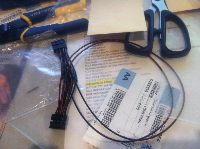
We need to lengthen these two wires...so we use the leftover cut wires to extend.
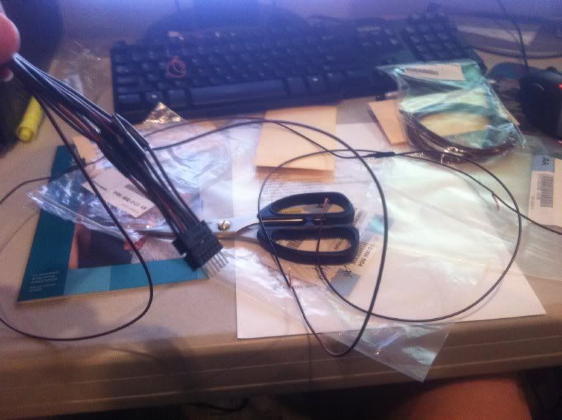
...repeat fan, join, twist, insulate process.
..I added three leftover cables to each wire. That make the two wires roughly 44" in length.
let's carefully pack it away and put it aside for now.
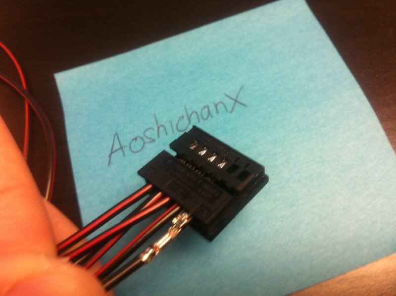
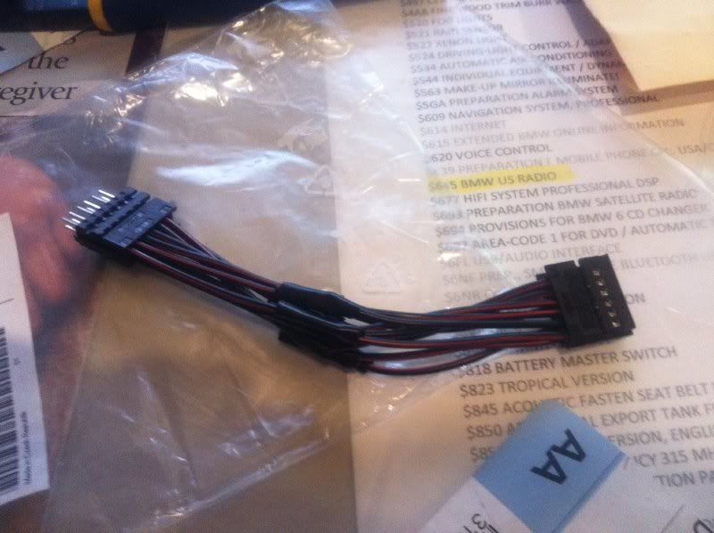
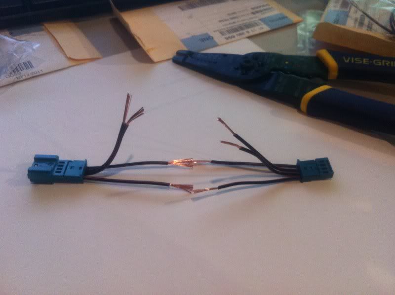
Now back to the shifter sockets. This is how they will look. Imaginary wires in between.
Plug-in male pins to the long socket like this:
Plug-in female pins to the short socket like this:
Adjust length of short one:
Adjust length of long one also:
Strip wires for both and they face each other like this:
Lift #2 and #3 up on both sides. Just say no to your dirty mind... Remember, #2 and #4 from the slipring harness will join #2 and #3 on the shifter harness, respectively. That is why we leave it alone for now.
Join #1 and join #4.
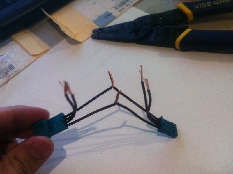
Join #1 and join #4.
Join #1 and join #4. Insulate.
Collateral damage...
 Installation Part 1 - Paddles to MFB
NOTE:
I miscalculated the type of pins needed. I didn't have enough male pins, so I ended up jury rigging the two ground connections. I basically took the ground pin out of slot #2 of both paddles, then stripped wire, wrapped it around the pin, and insulated with electrical tape. You will not have to do this. It will just be plug n play for you; you will just need to plug in the male pins.
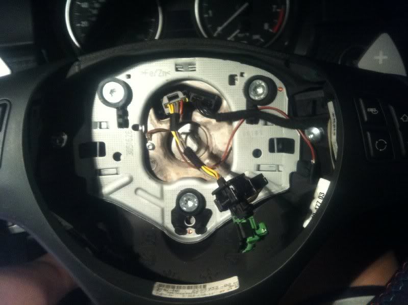
Take off your airbag. Remember to remove battery in trunk.
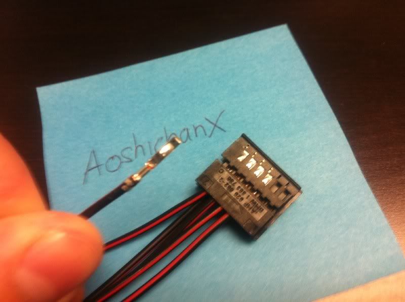
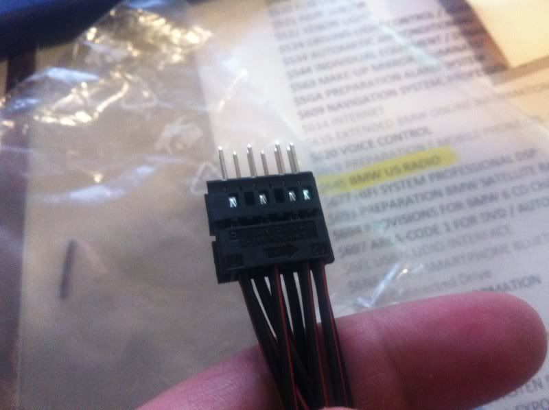
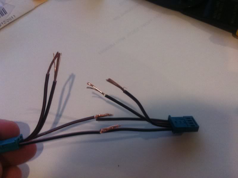
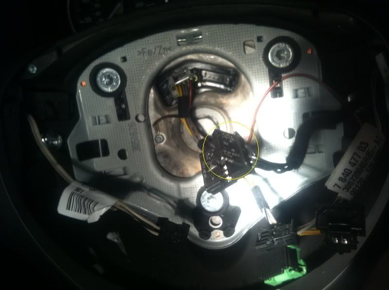
Here is a close up of the Paddle Harness. You can see the inscription #3, #2, and #1 above each slot.
Overview. Left paddle harness and Right paddle harness.
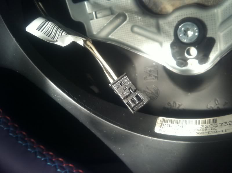
Let's take a look at the MFB. The red circle is where you wanna plug in.
The pin won't fit in. You will have to take out the MFB harness.
Take off the MFB
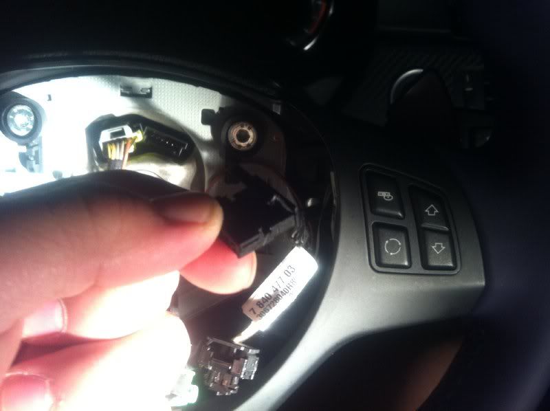
Unclip MFB Harness
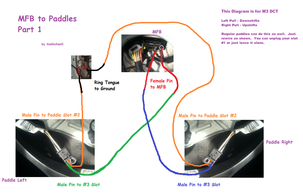
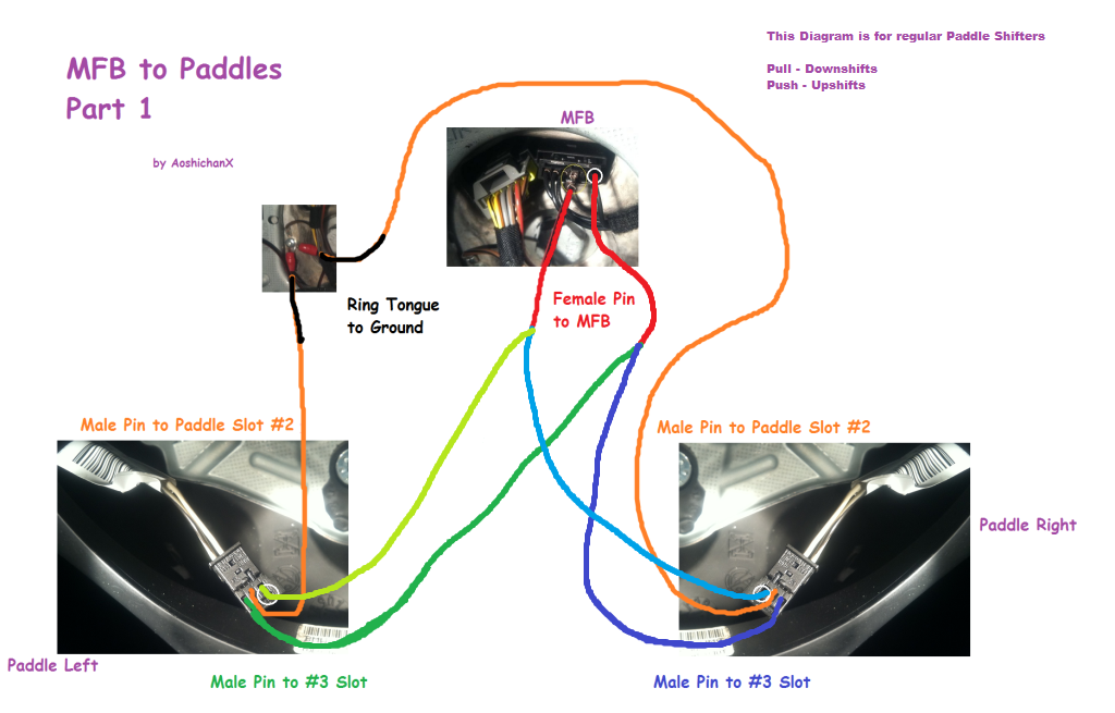
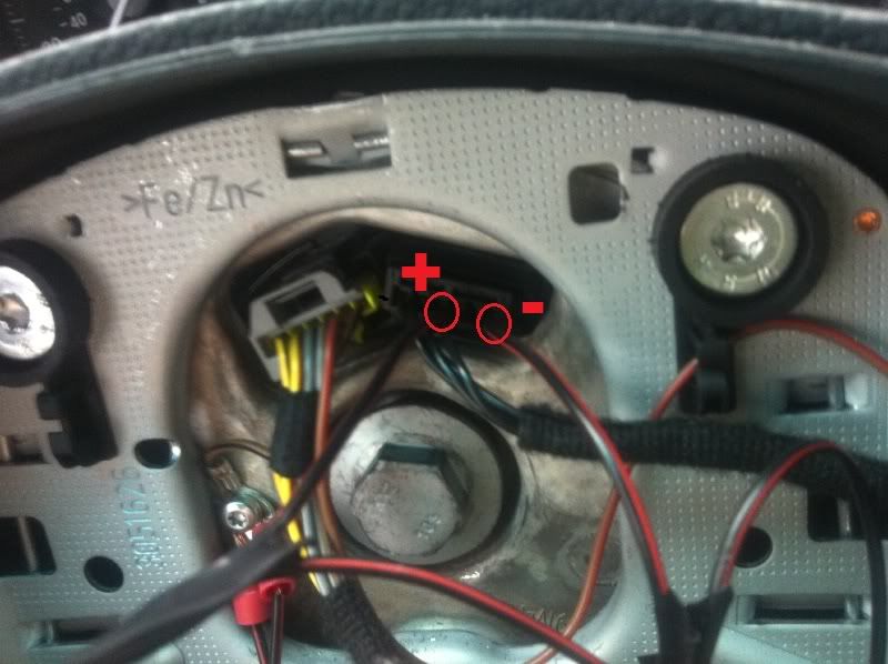
The 2 Male to Female wires. Plug the Male pin to the Left Paddle Shifter #3 slot and Female to the MFB Slot furthest right. For the other wire, plug the Male Pin to the Right Paddle Shfiter #3 slot and Female to the MFB Slot in the middle.
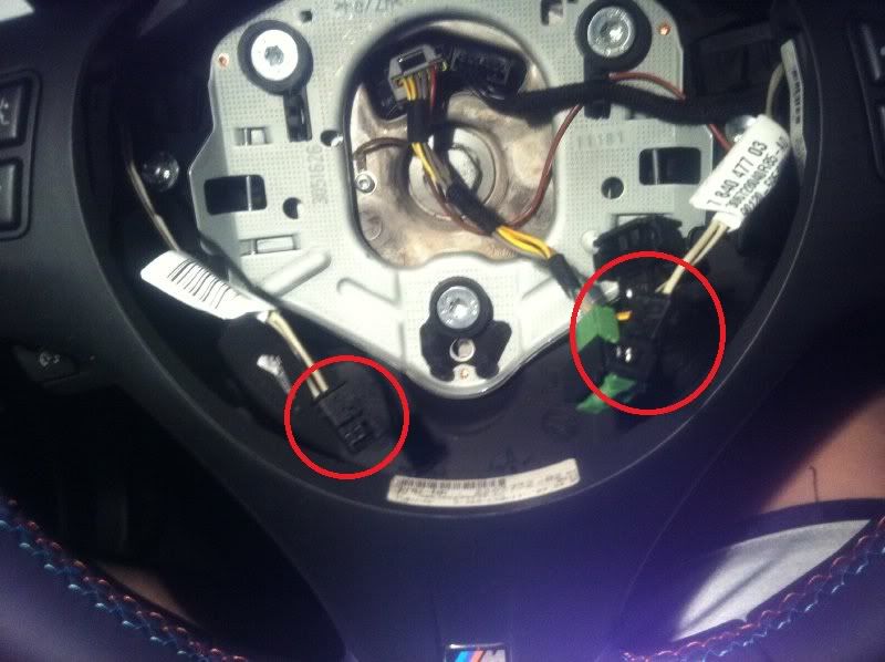
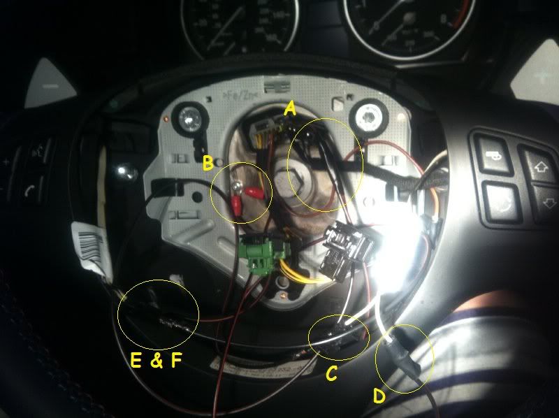
Next, take the two ring tongue wires we assembled earlier. Plug those in to the paddles and the ring tongues to the ground. Here is the final assembled picture.
A is the female pin to MFB.
B is ground.
E & F are the left paddle connections.
C & D are the right paddle connections. As stated earlier, I had to juryrig the ground connection to the paddles cause I ran out of male pin connectors. That is why
D is separated.
D is the connection from the paddle ground wire to the assembled ground wire.
 Installation Part 2 - Slipring to Shifter
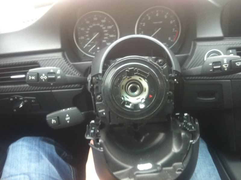
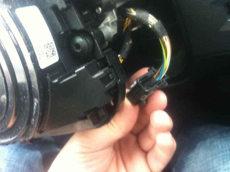
Take off wheel, view of slipring.
Slipring harness in view.
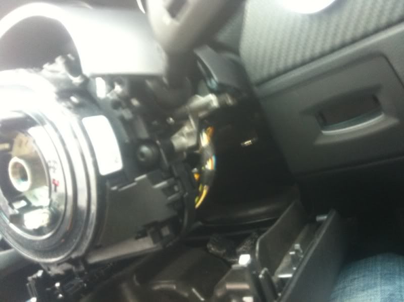
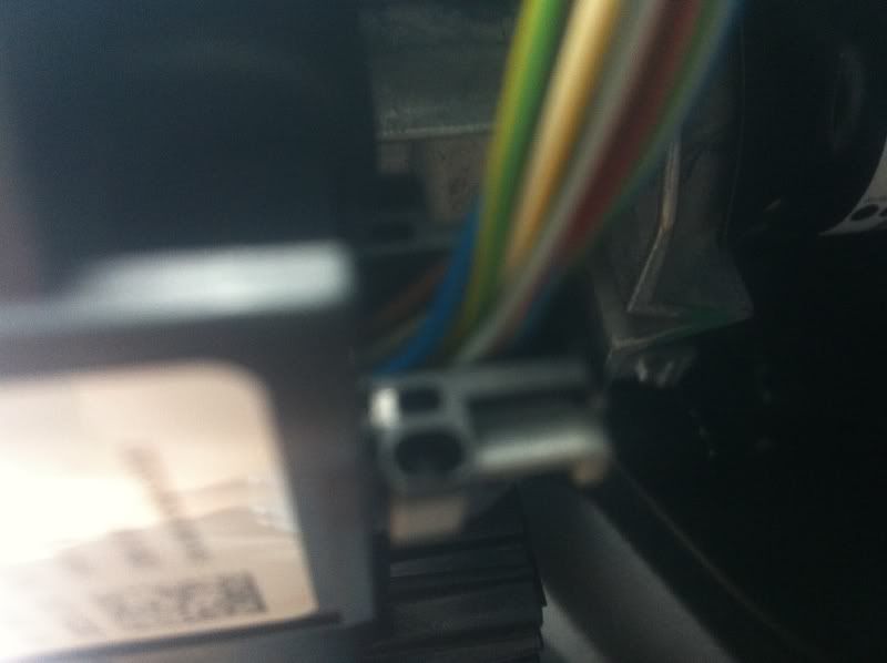
Blurry close-up of slipring harness.
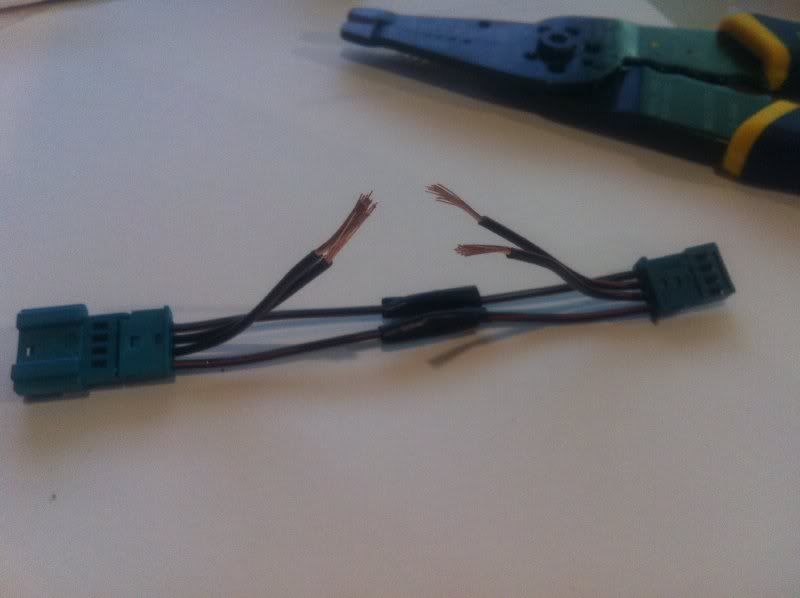
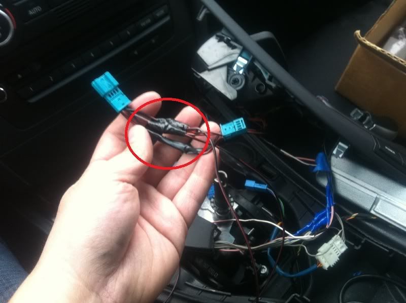
Slipring harness taken off.
Connect to PNP harness.
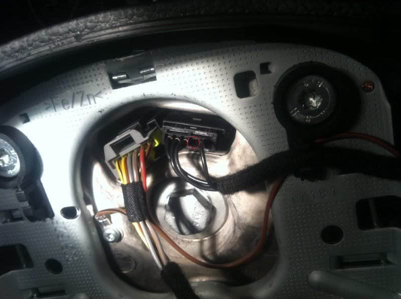
I am not using PNP harness, I decided to just plug in the wires directly to slots #2 and #4.
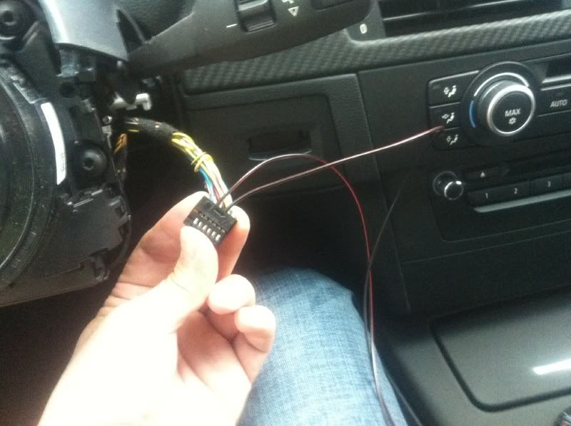
I am not using PNP harness, I decided to just plug in the wires directly to slots #2 and #4.
Took old wires out from #2 and #4. Insulate the unused wires.
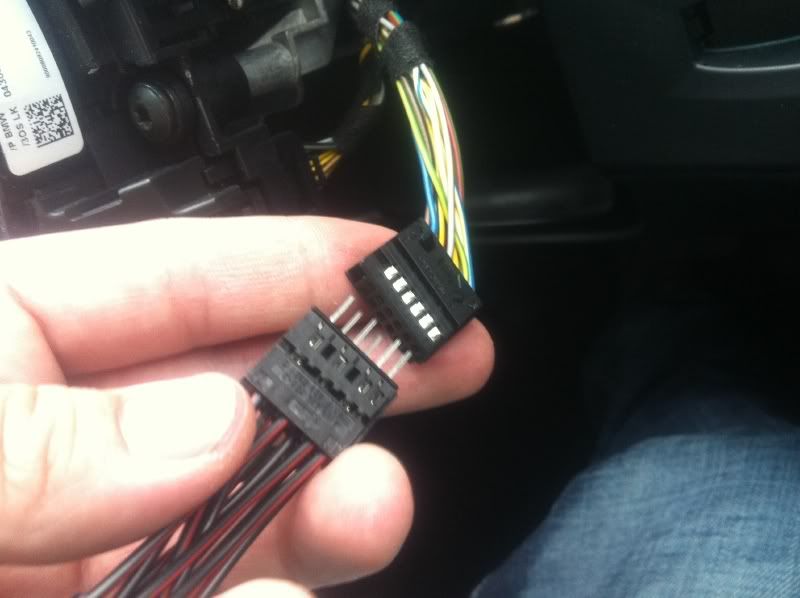
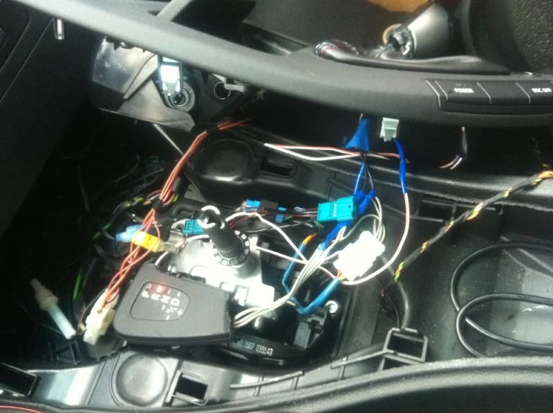
Ok let's take off the center console. See the blue connectors under the clip. We need to take it out and connect it to our harness.
Far away shot for perspective.
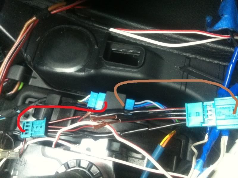
Disconnect the blue connectors and connect the ends to the new harness as shown.
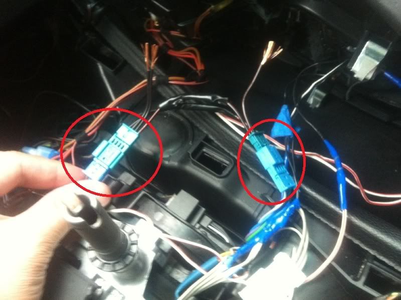
Disconnect the blue connectors and connect the ends to the new harness as shown.
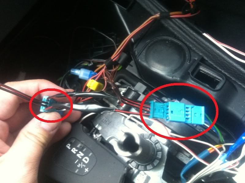
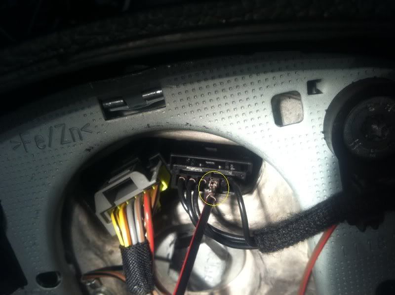
Connect #4 from slipring to #3 on the blue connector harness. Connect #2 from slipring to #2 on the blue connector. Insulate.
This is how mine looks once everything is connected.
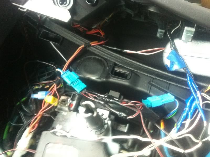
This is how mine looks once everything is connected and placed back.

Enjoy!
Installed Videos
Here are my finished installation videos: