There are 4 parts (so far) to this DIY.
Part 1: Wiring the module
Part 2: More details on wiring power (somewhat obseleted now with the new info provided in part 1)
Part 3: Hard-wiring audio
Part 4: Backup Camera
Part 1 (The other parts are different posts throughout this thread)
Time: about 2 hours
Tools needed:
Torx #10, #15, #20
Phillips head screw driver, flat head screw driver (BMW screwdriver)
Wire cutters/stripper
Multimeter (optional)
Materials needed:
14-18 Gauge wire to run power and ground
Tape (electrical)
Wire Butt connectors
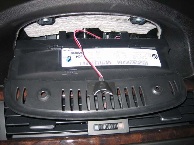
1. Unscrew the two screws (Torx #10) above the iDrive screen.
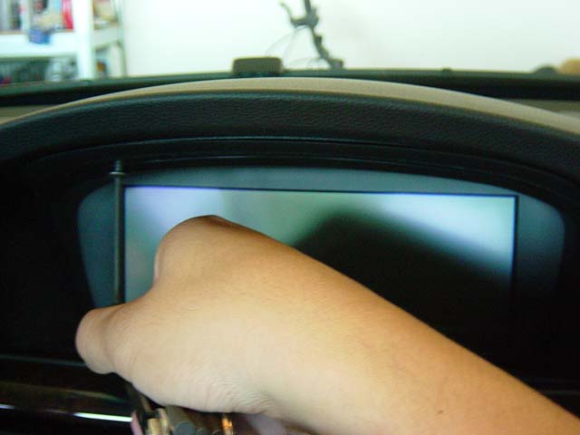
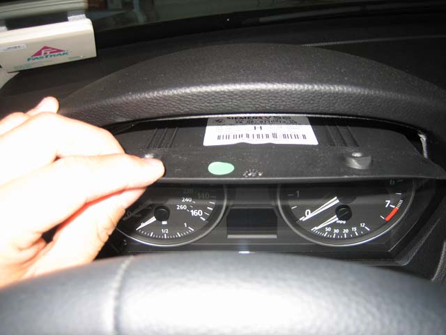
2. Pull the screen forward from the top edge to remove.
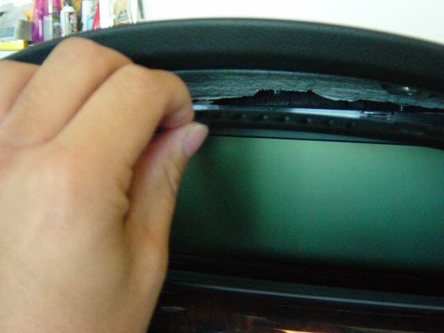
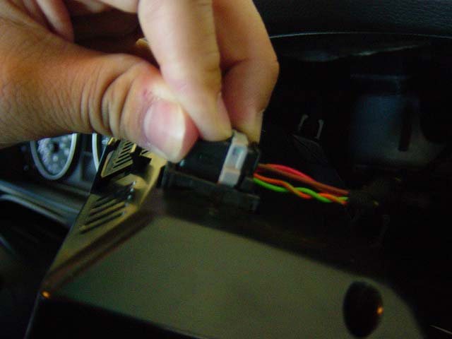
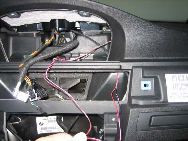
3. Disconnect the two cables in the back.
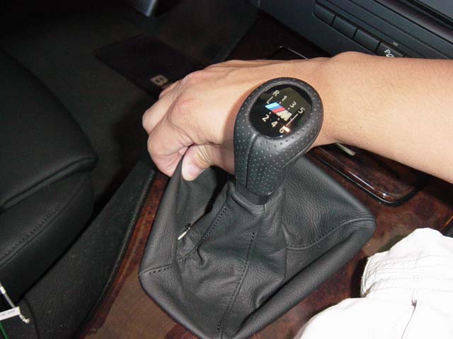
4. (OPTIONAL) You can skip the next couple of steps, but it makes it a bit easier to maneuver things around if you take out the center console trim. Start by removing the shift knob (unclip the boot and pull up HARD on the knob).
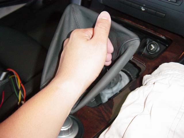
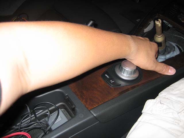
5. (OPTIONAL) Pull up on the center trim starting from the bottom part of the shift knob hole (toward the iDrive knob). It should pop right out.
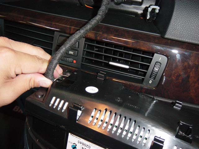
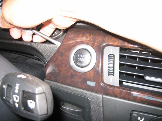
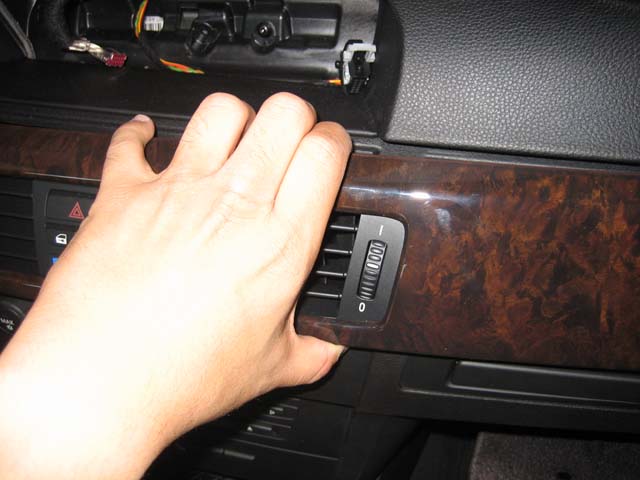
6. Now with the iDrive screen out, remove the dash trim starting next to the start button. You can use a flathead screwdriver to gently pry it out to start, but once you get a little gap, you can pull it straight off pretty easily.
7. Pull on the middle and the right side next to the passenger door (open the passenger door) to remove the rest of the trim.
8. Unplug three sets of wires behind the dash trim.
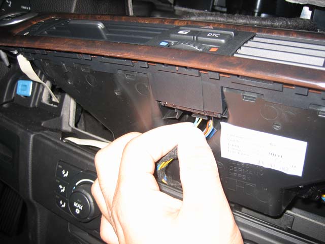
9. With the dash trim removed, the top of the climate control panel is exposed and can be pulled out.
10. Unplug the wires on the climate control panel.
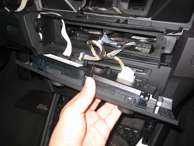
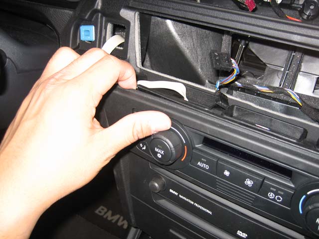
11. The top of the plastic faceplate of the dvd/cd drives is now exposed. Gently pull back on it to remove the faceplate.
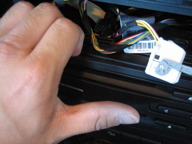
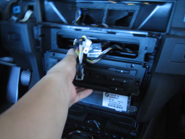
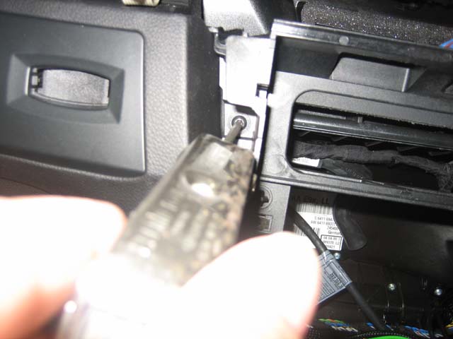
12. With the faceplate off, take out the four screws holding the silver radio unit in, then pull the entire unit (including drives) straight out.
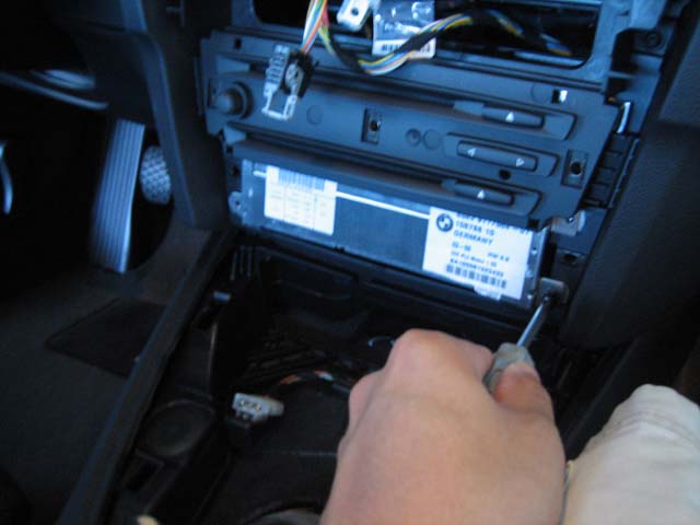
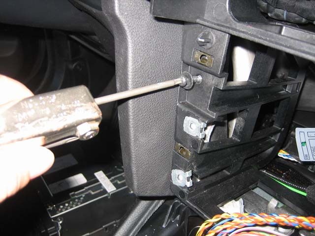
13. (OPTIONAL) The next step makes running the wires easier, but you can skip it if you have small hands and can reach through the trim and tiny holes. Using the Torx #15, remove the 4 screws holding the plastic surround around the radio hole. Unbolt the two bolts (8mm) on the bottom. The whole surround can now be removed.
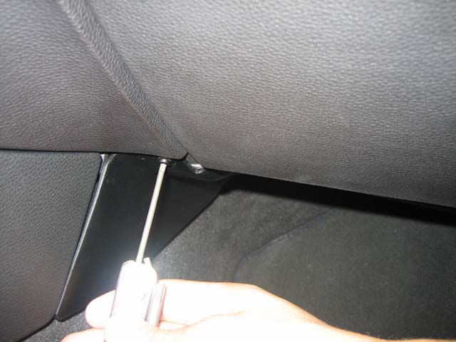
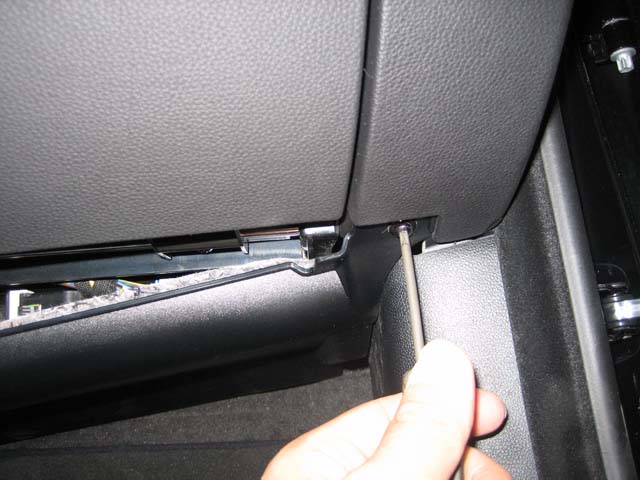
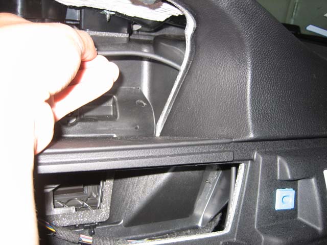
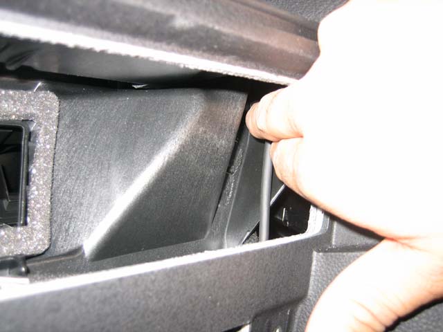
14. Remove the panel beneath the glove box by removing the two torx #20 screws.
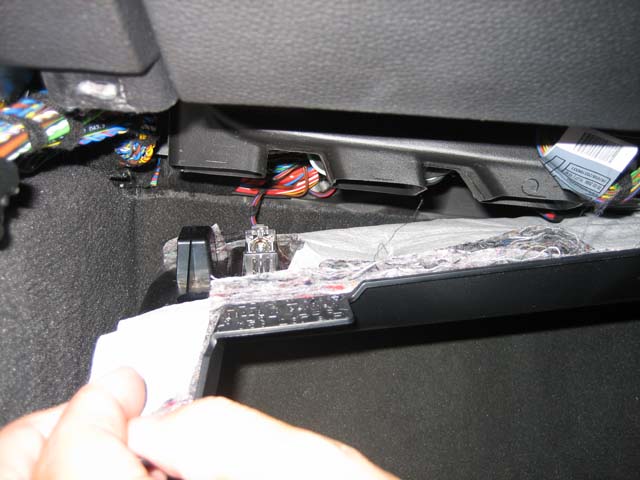
15. Now it's finally time to run some wires. Run the LCD wire provided in the kit from the iDrive screen hole, down to below the glovebox.
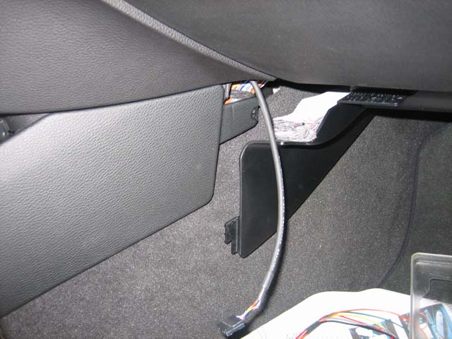
16. Run the IR reciever the same way from the iDrive hole down to below the glove box.
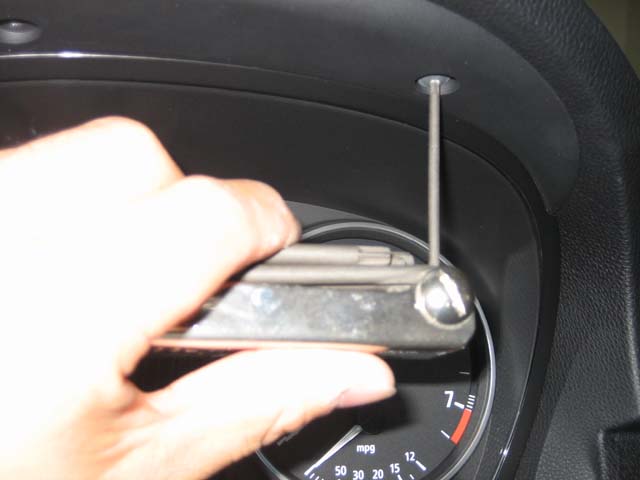
17. (OPTIONAL) Remove the speedometer in a similar way as the iDrive screen was removed (two torx #10 screws).
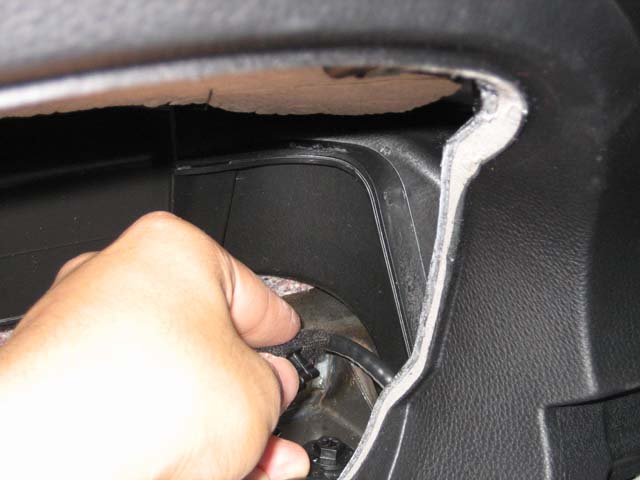
18. Remove the stock LCD cable (silver L-shaped connector, purple on one end, blue on the other). This is now going to run from the silver headunit to below the glove box to the nav2go module. This is a little easier to reach and manipulate with the spedometer removed. There is a clip in there that is holding the cable in place, but if you jiggle it hard enough, it will come off. Once you have this cable removed, run it from the headunit slot over to under the glove box.
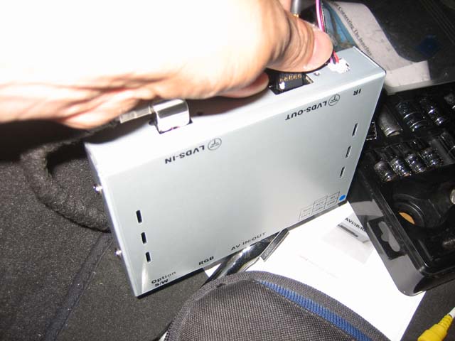
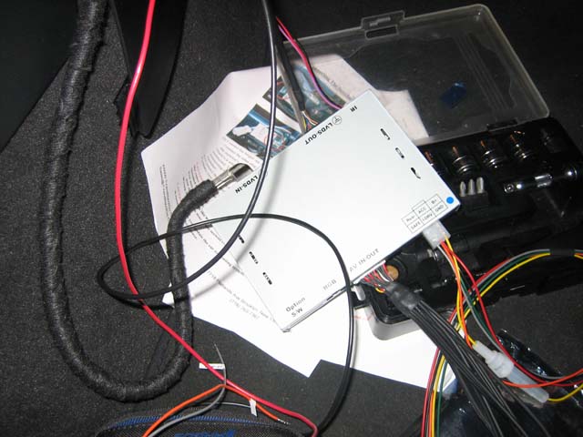
19. Now it's time to plug stuff in! Plug in the LCD cable provided with the kit into the LVDS out (white dot up), the stock silver L-shaped LCD connector into the LVDS in, and the IR reciever into the IR connector.
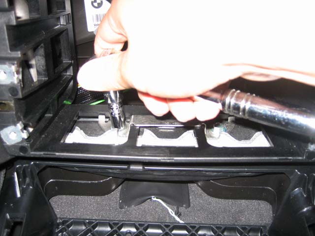
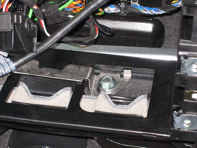
20. Now it's time to wire up the harness. Wire the black wire from the harness to your ground. A good ground is one of the 8mm bolts from step 13.
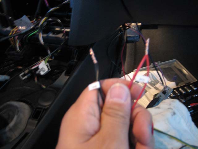
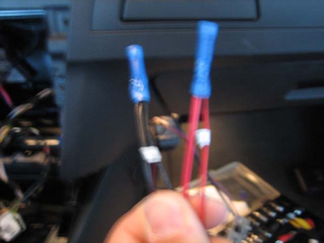
Connect the red ACC to a remote source, and the yellow, fused power wire to the hot +12V source. I used my remote line from my Line-output converter with built-in low voltage trigger, and wired the yellow wire directly to the fuse box using an add-a-circuit fuse-tap from autozone.
There are a few options for the remote... My method utilize a low voltage trigger that I already had for my sound system. Long used the middle pin from accessories power in the center console. This source is on when the engine is one --not in radio mode. Long also suggested that we use radio power. I could not find a source for this --I belive the radio may work like the factory amp does --constant +12V on, but +5V signals off, and +12V signals on. So I think maybe the best solution is the low voltage trigger --do a search on the forum... the low voltage trigger has been brought up many times before. The proper way to wire it is to wire the ACC to the trigger and the fused yellow wire to a constant +12V (i.e. the battery or the fuse box).
Edit: BMW06 has since discovered that the 7.5A mini-fuse in slot #5 in the fuse box acts as a great remote source that is on in radio mode. Use a fuse-tap for mini-fuse slots in this slot and wire it to the RED ACC line.
21. Now you can plug in the power harness and the AV input/output harness to the module.
22. Now you can start putting everything back together loosely so you can test your module. Plug in the provided LCD cable into the iDrive screen with the white dot to the rear of the monitor.
23. The last thing to do once it works, is to tape the IR reciever to the inside of your iDrive screen housing so that it's nicely hidden.
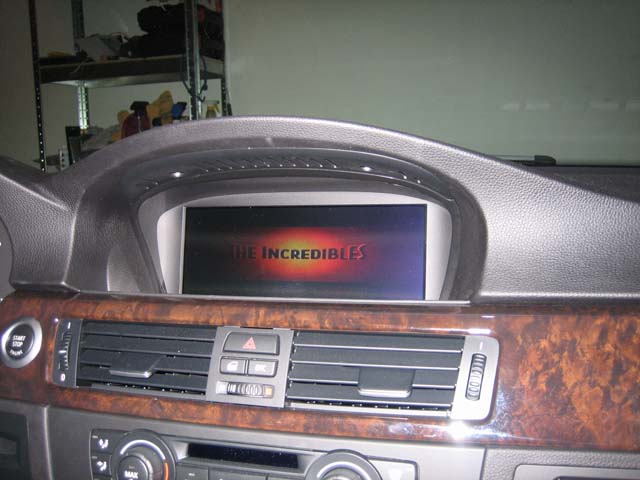
24. Finished! I'm using a PS2 for now... there really is no good place to put it because the slim PS2 has a flip-up dvd bay.
I'll add more to this DIY once I splice in the sound connection... for those who don't want to do it that way, you can just use one of those mini-jack to stereo RCA connectors to hook up the module to the AUX in in the center armrest.