|
|
|
|
 |

|
 |
BMW Garage | BMW Meets | Register | Today's Posts | Search |
 |

|
BMW 3-Series (E90 E92) Forum
>
DIY - Clown nose blinking LED
|
 |
| 06-23-2010, 10:06 PM | #199 |
|
First Lieutenant
 
28
Rep 375
Posts |
Like the blue color, adds a nice personal touch. Good job!
__________________
07 e90 335Xi, SB/Black, ZSP, ZCW, PDC
06 e91 325XiT, TS/Black, ZSP - Sold  |
|
Appreciate
0
|
| 01-10-2011, 12:49 PM | #200 |
|
Enlisted Member
 10
Rep 40
Posts |
Cleaned up with custom PCB
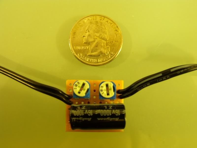
With many thanks to msinfo.us and Mr.5, I went a bit further with this DIY. I decided to learn how to make a PCB to make the device look much cleaner and less bulky to install. Below is a picture of my final product. I am still deciding whether it needs a small case to fit in, but I think it will be OK as is.
I had retrofitted my original mirror with a UGDO/Auto dim/Compass version, so I had that mirror to use on my bench for testing and delay set-up. What I found was that if I had the R1 resistor set at half its range and the R2 at about 1/8, I got a 3 second delay and a nice flash. Most of the parts I bought online through mouser.com. My cost for the prototype is probably about $100, but there were a number of initial things I needed to buy to make the PCBs and be able to test them. If anyone is interested, I would be willing to produce these for sale to the general public. I was thinking about $20 each including shipping in the US. Let me know. I have a video I made of mine on my bench prior to install which I may post later. |
|
Appreciate
0
|
| 01-12-2011, 10:14 AM | #201 | |
|
Captain
96
Rep 761
Posts |
Quote:
__________________
 |
|
|
Appreciate
0
|
| 01-14-2011, 05:37 PM | #203 |
|
Private
 9
Rep 91
Posts |
Seems that someone who has adjusted their pots to the appropriate frequency of blinking should post the resitance values. That way we could build boards using resistors instead of the larger, variable pots. My guess from the descriptions above and the circuit diagram is that EQUAL R1 and R2 values would result in a 50% duty cycle (ie - even off and on times) and the value of these should be around 4.7k or 5.1k. Can anyone confirm this? If so, e90inSC could fab his board with resistors, and make a nice, tiny, consistent package.
e90inSC: can you find a smaller ~15v 1000uF cap, then bend the leads 90 degrees to lay the cap on its side, or an axial cap, reducing the profile of the board? Something like this (http://www.parts-express.com/pe/show...umber=020-1714 OR http://www.parts-express.com/pe/psho...0-1048&scqty=1) Last edited by BrynDN; 01-14-2011 at 06:00 PM.. |
|
Appreciate
0
|
| 01-14-2011, 09:35 PM | #204 |
|
Private
9
Rep 91
Posts |
Did some more research on this. Turns out my guess was wrong...go figure (This also means that the remainder of this post could be completely off, too
 ). Duty cycle is actually a ratio of R1 and R2 as follows: ). Duty cycle is actually a ratio of R1 and R2 as follows: The chart shows the frequency that the output will blink, which is based on the size of the capacitor and the total of R1 (=Ra) and R2 (=Rb). Laymen's terms: Given e90inSC's prior testing that "Pot 1 should be about 50% (~5000 ohms) and Pot 2 should be about 1/8 (~1250 ohms)." I'd say the blinking that we're after is around a 10-15% duty cycle (ie - the light is on 10-15% of the time, the rest of the time it's dark). To achieve this there are many possible values of Ra and Rb, but one possible solution is Ra=75000ohms and Rb=12000 ohms. This results in a 12.1% duty cycle. Now, looking at the frequency chart and using my solution for Ra and Rb, since Ra + 2*Rb = 99000ohm we'll follow the 100k line. This would indicate that to achieve a flash every 1 second (1Hz), we would want to use approximately a 20uF cap. In the video at http://www.youtube.com/watch?v=kX49v7KPODg the frequency is about .6Hz (the LED flashes 24 times in 39 seconds). To achieve this, the chart would indicate that a 68uF capacitor would be approximately correct. In e90inSC's design, his total Ra + 2*Rb = ~7500 ohms. If we follow an imaginary line between 10k and 1k ohm, this seems to align with his experience that a 1000uF results in a flash about every 3 seconds (or .333Hz). Net result: I think a value for R1 of 75k ohms, a value for R2 of 12k ohms, and a capacitor with a 68uF (16V rating would be fine) would achieve the results we're looking for, in a smaller package than some of the above designs. I might get around to trying this this weekend, but I wanted to post it in case anyone else wanted to play, too. Also, for those of you not so inclined to build your own circuit, check out this video: http://www.youtube.com/watch?v=mNDu5...1&feature=fvwp. Not quite as pretty or consistent, but works... For reference, here's the document I got my information from. The mode we're looking at is "astable." http://www.national.com/ds/LM/LM555.pdf Last edited by BrynDN; 01-16-2011 at 11:24 AM.. |
|
Appreciate
0
|
| 01-15-2011, 08:58 AM | #205 |
|
Enlisted Member
0
Rep 41
Posts |
Duty cycle
@BrynDN
Okay so I just setup the circuit on the breadboard. C1=47uF, R1=1K, R2=10k Duty cycle is 52%. Frequency is 1.4Hz. Very close to what we want and the human eye probably won't notice the difference of the real alarm and the circuit hack next to each other. Here's a handy calculator that you can input different values for R1, R2 and C1 to derive different frequency and duty cycles: http://xtronic.org/download/555-time...ent-selection/ Last edited by john_e90bimmer; 01-15-2011 at 09:20 AM.. |
|
Appreciate
0
|
| 01-15-2011, 03:01 PM | #206 | |
|
Private
9
Rep 91
Posts |
Nice work. So you went with a 50% duty cycle? I haven't seen an OEM alarm LED flashing, but the video I saw on youtube from earlier in this thread looked like a much lower value (very brief flash followed by a 1.5 second or so pause). Have you seen an OEM alarm? Do you think it's close to the same amount of time on as it is off?
Quote:
|
|
|
Appreciate
0
|
| 01-15-2011, 05:43 PM | #207 | |
|
Enlisted Member
0
Rep 41
Posts |
Quote:
Last edited by john_e90bimmer; 01-16-2011 at 01:15 PM.. |
|
|
Appreciate
0
|
| 01-18-2011, 04:59 PM | #209 | |
|
Enlisted Member
0
Rep 41
Posts |
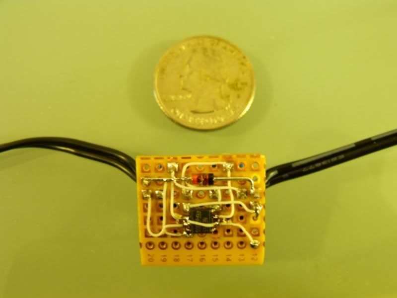
Quote:
 Nice work. I like the bottom side of the board, looks very clean and neat with the substitution of the SMD chip. Nice work. I like the bottom side of the board, looks very clean and neat with the substitution of the SMD chip. |
|
|
Appreciate
0
|
| 01-18-2011, 09:08 PM | #210 |
|
Enlisted Member
10
Rep 40
Posts |
Love the size. Using wires can make the device smaller since you don't have to worry about crosses. One thing I found last weekend is that there was no wire that went high after the ignition was shut off. The wire they mention earlier in this post doesn't do what they thought. In my '09 328i it stays at .5V. So I added a SPDT relay to switch the circuit on and off. Would love to know if you found a usable source wire in your vehicle.
|
|
Appreciate
0
|
| 01-20-2011, 07:09 PM | #211 |
|
Private
9
Rep 91
Posts |
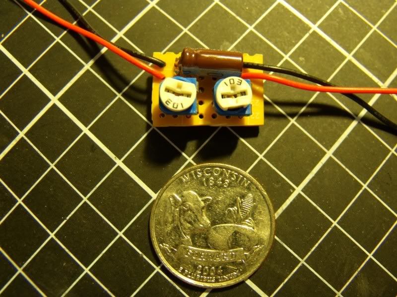
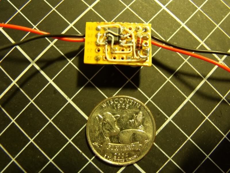
I built the circuit with R1=22k, R2=1k, and C=68uF (16V). Seems to be a good frequency and duty cycle, maybe a little too fast. Debating between 100uF (slightly slower) and the 68uF in the video. Also, you can see how much smaller the cap is than the 35V, 1000uF cap others are using.
http://www.youtube.com/watch?v=iCPf5IRRIuQ Last edited by BrynDN; 01-20-2011 at 07:36 PM.. |
|
Appreciate
0
|
| 01-22-2011, 04:40 PM | #212 | |
|
Enlisted Member
0
Rep 41
Posts |
Quote:
If you want to go small check this out: http://www.mouser.com/ProductDetail/...MDv5e8CxV80%3d |
|
|
Appreciate
0
|
| 02-07-2011, 03:47 AM | #215 | |
|
///M at Heart

90
Rep 1,954
Posts |
Quote:
I'm not very good with making circuit boards so I'd rather not make it myself. |
|
|
Appreciate
0
|
| 02-12-2011, 12:49 PM | #216 | |
|
Captain
96
Rep 761
Posts |
Quote:
I'm in too. Would like one, but haven't heard a word...
__________________
|
|
|
Appreciate
0
|
| 02-17-2011, 09:57 AM | #217 | |
|
Enlisted Member
0
Rep 41
Posts |
Quote:
|
|
|
Appreciate
0
|
| 03-04-2011, 09:40 AM | #218 |
|
Brigadier General

300
Rep 3,969
Posts |
so who is selling these thingies?
__________________
Mobridge DA2 > JBL MS-8 > ARC XDi 600/4 > JBL Gti 408 Mids & Vifa OT19 Tweeters; PG Ti2 1600.5 > Morel HCW-10 & IDMax 15
|
|
Appreciate
0
|
| 03-10-2011, 08:13 AM | #219 |
|
Registered
0
Rep 1
Posts |
Hello there
Nice DIY  I have one problem understanding just where have you placed the negative (-) terminal. You said: "Connect positive (+) wire from the timer you built in step One to number one connection on 1-14 black plug and negative (-) wire to ground (I used bolt near motor)." What motor are you talking about? Thanks in advance. |
|
Appreciate
0
|
| 03-30-2011, 03:00 AM | #220 | |
|
ಠ_ಠ
74
Rep 1,539
Posts |
Quote:
|
|
|
Appreciate
0
|
 |
| Bookmarks |
|
|