

|
|
|
|
 |

|
 |
BMW Garage | BMW Meets | Register | Today's Posts | Search |
 |

|
BMW 3-Series (E90 E92) Forum
>
Reverse engineering E9x xDrive for an AWD E36 project: a series
|
 |
| 12-30-2023, 04:39 PM | #1 |
|
New Member
0
Rep 14
Posts |
Reverse engineering E9x xDrive for an AWD E36 project: a series
Hey everyone, thanks to Leucosticte with the wiring schematic I am off in the right direction on reverse engineering the E9x xDrive operation, namely controlling the ATC300 transfercase actuator.
Ill use this thread to document the progress, in the video below we disassemble the xDrive actuator from the transfer case and dissect its operation from a high level. More to come! Project AWD E36 xti: Subaru DCCD vs BMW xDrive actuator Part 1 Last edited by AdamPE21; 03-02-2024 at 05:18 AM.. Reason: URL embed fix |
| 12-30-2023, 07:30 PM | #2 |
|
Captain
 638
Rep 766
Posts |
Neat. Hope you figure it out.
There is probably a proxy sensor on the motor shaft the computer uses as feedback for "% center clutch engagement". It's not terribly complicated, but no idea if there is something commercially available that can operate it. Beyond my ability to fabricate. Might be stuck programing a raspberry pi to 'apply voltage to motor until hall sensor clicks X times for 50% engagement' or something like that. Presumably there is also a hard mechanical stop in the disengaged position, and the computer uses current feedback (locked rotor) to 'find home position' The ATC300 slightly overdrives the front axle, so the T-case is never really 'locked'. The difference in rotating speed at the wet clutch is what pushes 'torque' to the front tires. Might make for some interesting driving dynamics if you manually force it to maximum engagement for an extended time. Might be necessary to consider some sort of fluid cooling arrangement if it's going to be run that hard as well.
__________________
Sometimes a bolt is just a bolt.
|
|
Appreciate
0
|
| 12-30-2023, 07:43 PM | #3 |
|
New Member
0
Rep 14
Posts |
Yeah there is a position pulse coming off the actuator and Ill use some current sensing to figure out whether the motor is moving or not
the challenge will be keeping the actuator from overheating when we want 50/50 bias or 100% lockup. Not sure about measuring clutch or fluid temp though
|
|
Appreciate
0
|
| 01-03-2024, 12:30 PM | #4 | |
|
New Member
0
Rep 14
Posts |
Quote:
|
|
|
Appreciate
0
|
| 01-03-2024, 06:52 PM | #5 |
|
Captain
638
Rep 766
Posts |
I could be wrong. Meant to take my old one apart... but never got around to it. Eventually got tired of it sitting in the garage and set it to the scrap yard.
I did paint-mark the flanges and gently spin them by hand counting rotations. Ended up being something like 51/50 front/rear. Remember getting about the same when turning the rear or front outputs. Makes sense given that there is no differential in the T-case. Just a wet clutch takeoff from the main driveline. Also jives with people putting larger rear wheels on X-drives, start getting shuddering/bucking. If the wheel angular speeds differ the correct amount that the front and rear outputs are nearly the same, the clutch has a tendency to lock instead of slipping continuously. With all 4 wheels on the ground, the clutch disks attached to the front spin slightly more slowly, so closing the clutch down applies a forward torque to the axle while under continuous slip.
__________________
Sometimes a bolt is just a bolt.
|
|
Appreciate
0
|
| 01-12-2024, 05:34 AM | #6 |
|
New Member
0
Rep 14
Posts |
Part 2 is complete! I have a good idea of the sensor circuit characteristics in the xDrive actuator now and can start designing a system. About 42% of the way there, but can start making a schematic for the controller hardware and play with some software.
AWD E36 Project xti: Reverse Engineering xDrive Actuator Circuits|ATC300 Transfer Case Sensors Pt 2 Next up we will be putting the actuator back together and mounting back to the transfer case to characterize the system as a whole. Last edited by AdamPE21; 03-02-2024 at 05:22 AM.. Reason: URL fix |
|
Appreciate
0
|
| 01-12-2024, 10:20 AM | #7 |
|
Captain
638
Rep 766
Posts |
I do not think you are correct about the motor being back-driven by clutch spring force.
That's just not how worm gears work. The output of the worm cannot be driven by the spur. It's just the mechanical nature of the various gear ramp angles. That's also not how traditional armature DC motors work. They don't do continuous locked rotor service. It would need to be a stepper motor for that. The torque you're measuring is probably a slip-clutch somewhere in the assembly... or it's just spinning on a set screw. I'm open to being shown wrong, it's possible if the gear ramp angles are 'slippy' enough, but that would be better solved with a different type of gearset. Just speaking from a long life of general engineering experience... but I'd recommend seeing if the actual rotor is spinning when you force the actuator pinion to turn before you get too deep into the electrical control design. Perhaps bolt it up to the T-case on the workbench, spin the rotor by hand then see if it spins back.
__________________
Sometimes a bolt is just a bolt.
|
|
Appreciate
0
|
| 01-12-2024, 10:29 AM | #8 |
|
Captain
638
Rep 766
Posts |
Literally the first two google results...
https://robomechjournal.springeropen...oth%20surfaces. https://www.reddit.com/r/robotics/co...ld_this_be_an/ So it can be done. One uses vibration, the other carefully chosen gear angles and slippy plastics. But the choice of a DC motor doesn't match the application, nor the high breakaway/low running torque on the output pinion. The running torque should be highly variable when pushing a 1:100 or more gear increase. Particularly with a heavy DC rotor on the worm output. I'd expect to hear or feel the rotor spinning. I dunno... but if it was me, I'd do a few more experiments.
__________________
Sometimes a bolt is just a bolt.
|
|
Appreciate
0
|
| 01-12-2024, 05:01 PM | #9 |
|
New Member
0
Rep 14
Posts |
I agree it sounds ridiculous, but one of the first things I checked was backdrive of the actuator system
about 9Nm breakaway and 1.3Nm running load. Also the schematic in the BMW ETM only shows ground on the brown wire circuit. Taking motor apart it is truly a brush DC motor. The more I dig into this, the simpler it looks. I think the most difficult part will be getting a corresponding PWM duty cycle to match up with a given lockup percentage. At the very least, I might only use PWM to modulate/transition between 0% and 100% lockup when needed.
|
|
Appreciate
0
|
| 02-10-2024, 12:37 AM | #10 |
|
New Member
0
Rep 14
Posts |
Spent some time this evening with a newly acquired oscilloscope, some circuits and the actuator assembled to the transfer case as a system. Learned some interesting things!
1) The actuator pulls more than 20A at stall current, but running load from 0 lockup to where it starts getting resistance is about 3A. Can someone tell me the fuse size for xDrive or transfer case on their E9x? 2) The TC will return to a zero lockup position on its own, simply by pulling power (this is great news!). No need for h-bridge or reversing polarity. 3) Running the motor at 100% duty cycle or directly to 12V will result in the entire transfer case physically locking up. Impossible to turn anything by hand! This was a big surprise. It makes me wonder what would happen to the system if the high voltage was shorted to ground. 4) I PWM'd at various frequencies and blew two FETs in the process, eventually realizing after the first few cycles of pulse the motor hit the end of travel and stalled and overheated my FET (without a heat sink). Eventually found all the way down to 19% duty cycle at ~70Hz (the lowest my function generator could go for %) it still locks. Tomorrow I'm going to try some higher frequencies to see if I can get more resolution out of the duty cycle. I think I am running into a capacitance issue on the gate of the FET...or my function generator output isn't running properly because at high frequencies the waveform started looking more like a sawtooth than square wave. Blue is current (5V indicates >20A, stalled even with PWM) and Yellow is the FET PWM gate signal. 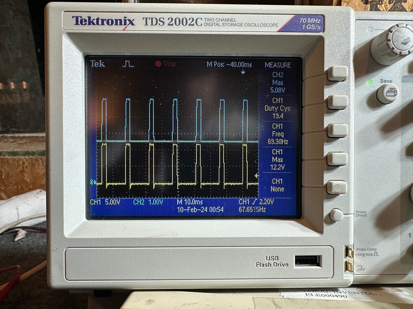 |
|
Appreciate
0
|
| 02-22-2024, 11:31 AM | #12 |
|
Enlisted Member
 5
Rep 31
Posts |
Following this thread (I commented on your YT video). Very excellent work, I'm starting the process of working on an ATC35L. It would be interesting to see of the motor has similar parameters or not.
Any idea of how the TC returns to 0 lock on power open? Is there springs or something in the transfer case? I know from x deletes documentation that there is still very small amounts of torque transfered in the open position due to some force transfer from the fluid. |
|
Appreciate
0
|
| 02-23-2024, 02:12 PM | #13 | |
|
New Member
0
Rep 14
Posts |
Quote:
|
|
|
Appreciate
0
|
| 03-02-2024, 05:27 AM | #14 |
|
New Member
0
Rep 14
Posts |
Progress report - assembled the actuator back to the ATC300. Did some system level characterizations with the o-scope and have decided PWM isnt going to be practical (once the TC actuator starts moving it basically takes it to full lock just slower). Agree with going down the pure DC path and will build a pulse counting program for the controller and monitor current feedback. Biggest question I have is at what current does the TC get to 100% (a straight DC 12V stalling the motor does something interesting, but dont want to drive it this way!).
Going to shift gears on the project to disassembling the E36 and E46 donor car. Will check back in a few months on here when I build the controller. AWD E36 Project xti: xDrive reverse engineering Pt 3 | System level testing with an Oscilloscope! 4K |
|
Appreciate
0
|
| 03-04-2024, 07:25 AM | #15 | |
|
First Lieutenant
205
Rep 345
Posts
Drives: 2007 BMW 328xi E92 6mt swap
Join Date: Oct 2019
Location: New Jersey
|
Quote:
Make sure to check the data sheet of the FET and see if its suitable too. |
|
|
Appreciate
0
|
| 03-06-2024, 04:38 AM | #16 | |
|
New Member
0
Rep 14
Posts |
Quote:
 ) as it would be up over 200°F in just a few seconds which matches what I was seeing. ) as it would be up over 200°F in just a few seconds which matches what I was seeing. |
|
|
Appreciate
0
|
 |
| Bookmarks |
|
|


