

|
|
|
|
 |

|
 |
BMW Garage | BMW Meets | Register | Today's Posts | Search |
 |

|
BMW 3-Series (E90 E92) Forum
>
PCV (Positive Crankcase Ventilation) - saga continues :)
|
 |
| 04-18-2011, 03:24 PM | #1 |
|
Banned

271
Rep 5,876
Posts |
UPDATE (July 27, 2011):
========= No idea how I/we missed the fact that the AR OCC is right in BMW spec, with upgraded turbos on the car, as stated in the Bentley service manual...in fact, running without the AR OCC and on the stock PCV setup makes the car go into vacuum (as shown in the data in this thread) when the expected crankcase pressure, again according to Bentley BMW N54 specs, is between 2.8-4.4" of H2O...Here's the source of some of the recent discussion on the topic: http://www.e90post.com/forums/showpo...7&postcount=63 The BSH OCC is also very close to spec, just borderline out of spec due to just slightly larger crankcase pressure (1" H2O)...that is with upgraded turbos...with stock turbos I'd say that it'd be within the BMW spec and is perfectly safe to use... In summary, both BSH and AR OCC are safe to use with the upgraded (RB) turbos as their crankcase pressure under WOT conditions is within BMW specs..on stock turbos, which haven't been tested for crankcase pressure, I'd expect both OCCs to be even tighter within BMW spec Enjoy your BSH and AR OCCs ppl, they work just fine... My personal vote/preference, on upgraded turbos, goes to the AR OCC driver's side mounted version  ===== Thought I'd start a new thread and not pollute the BSH OCC thread with PCV discussion so no one gets offended  lol The post below is copied right from the BSH OCC discussion thread so for any prior feedback please refer to the following post (you can go a few pages into it when it starts to get into PCV discussion): lol The post below is copied right from the BSH OCC discussion thread so for any prior feedback please refer to the following post (you can go a few pages into it when it starts to get into PCV discussion):http://www.e90post.com/forums/showthread.php?t=513999 Here's a diagram of the N54 PCV system to start off the discussion with: 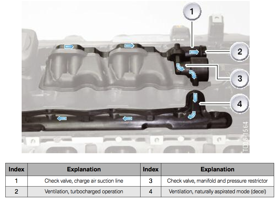 There are 2 checkvalves, in the diagram #2 and #3..unless you're running VERY high boost and upgraded turbos you probably don't even need to read this post Here we go: - if functional, cv#2 is open under boost (acceleration) and "vents" air out of the crankcase with any blowby, oil vapours. It is CLOSED in all other conditions. Let's call this cv the OCC checkvalve as that's what most people know about today as OCCs hook up on them. - if functional, cv#3 is open under vacuum (idle, cruise, deceleration) and sucks air out of the crankcase, through the cyclonic BS in the valve cover and in it goes into the intake manifold, and goes right through your intake valves and gets burned off. It is CLOSED in all other conditions. Lets call this checkvalve the intake manifold checkvalve. This is THE checkvalve we've just started talking about past few days, not many people have ever discussed it and no one ever hooks anything up on it as its vacuum based. So, the two checkvalves operate in different situations, one is under BOOST other is VACUUM. So, to have crankcase overpressure "issues" 2 things can happen (both are possible but 2nd is much more likely): 1) You "can" get OVERpressure when/if CV#2 remains closed open under boost OR whatever is hooked up on it is restrictive (like a restrictive breather, OCC). Both of these are bad. Likelyhood of CV#2 clogging or not opening for any reason is EXTREMELY low. I know this by looking at it. So no issues with keeping it in place. What needs to be investigated here is CFM out of the crankcase under boost and compare that to how restrictive alternative setups are (OCC, breather, VTA). They might be just FINE! but given no OCC vendor has ever published ANY data, we have no idea..willing to risk it with your car? sure, your car, myself been guilty of this for 2.5 years now I'm trying to actually understand it with some data2) You "can" get OVERpressure when/if CV#3 leaks under boost. Now, this one MUST stay CLOSED under boost which theoretically it "should". If its NOT closed as it should be, what do you think happens? It allows air to leak into the crankcase from the intake manifold (which is under positive pressure/boost). This causes 1) a boost leak 2) crankcase to pressurize with air that was meant to go into your engine instead of bypass it and enter the crankcase through this damn little checkvalve Keep in mind BMW designed this system with stock turbos in mind and much much lower boost than some of us are willing to run on these carsHow and why do I suspect checkvalve#3 to be prone to leaks under boost? Given some failures of turbo seals, various gaskets on cars especially with higher boost applications, and myself on my car noticing oil leaks all over my engine recently, ONLY when under high boost, I'm strongly suspicious of the operation of this. I washed down my engine bay, lowered boost, and no oil leaks anywhere after extended runs/pulls. The only conclusion I can draw from all of the above is that CV#3 is leaking when under very high boost, causing crankcase overpressure which causes oil to go past various seals on the car (turbo, engine) which is B-A-D! I've written all of this before and this time I really really tried to explain it as well as I can. If anyone has any further questions I'll refer them back to this post as I really can't explain it any better. Anyone still confused after reading this just try reading it again it'll eventually click. Referring to the diagrams posted also helps when reading it... Now, there's no BEST solution here. There are only options. VTA is illegal and smelly but max performance is provided due to great seals under boost, and there's next to no maintenance. OCC/closed setups are legal, not smelly but maintenance is required and performance is not maximized as sealing isn't maximized. Also, when it comes to strictly horsepower, vacuum is critical. Now, this isn't the vacuum that CV#3 provides in stock form. Its also not vacuum from cv#2 as that one doesn't have ANY in the first place. This would be a vacuum provided by an additional aftermarket vacuum pump hooked onto the valve cover somewhere (maybe that's on top of checkvalve#3, but maybe not). This vacuum needs to be applied even when accelerating/boosting, and a vacuum pump would do this job. It would ensure a good engine seal everywhere and when your engine seals really well it makes much better power. A big trick here is to "know" how much vacuum to pull as there is a thing called "too much" vacuum that can also be damaging. But this part of the story we can look at solving later... EDIT: Actually if someone is willing to help me recommend a vacuum pump setup that'd assist in providing good seal to this engine under boost that'd be awesome...looking for pump recommnendation, how to set it up, possible mounting location, where to hook it into the valve cover, etc etc. Last edited by dzenno; 07-27-2011 at 10:33 AM.. |
| 04-18-2011, 03:48 PM | #2 |
|
Banned
271
Rep 5,876
Posts |
First thing to do is find a place in the valve cover to install a vacuum gauge, run it inside the cabin/dashboard and see where we stand with crankcase pressure under various boost conditions (low, medium, high). This would also tell us a complete story on any overpressure conditions as well as restrictiveness of any current OCC setup vs stock, or for that matter, lack thereof.
Any suggestions? |
|
Appreciate
0
|
| 04-18-2011, 03:54 PM | #3 |
|
Major
 94
Rep 1,184
Posts |
Easiest and cleanest solution I propose:
1) block closed the CV #3: simply unscrew the round cap that closes the cylinder under the line coming from #3 on the picture, in the centre of it plug a cap (I used a 6mm silicone hose piece long 15mm with a screw) sorry no picture, but if you open it you will understand it is logic and easy. 2) remove CV #2 and either: A) Hook up a 1" rubber pipe the length of the car to vent it on the back of the car B) hook up the end of this pipe in the exhaust with an special inlet to use the Bernoulli scavenging force to create a little vacuum C) hook up a vacuum pump... no advice or experience. D) hook up an effective but NOT restrictive OCC If you hook up a piece of 1" pipe, there will likely be atmospheric pressure in the crank-case, it is not optimal but ok If you hook up a restrictive OCC pressure will build up from blowby and boost passing the rings, this is bad for the engine (seals, valve seals etc) |
|
Appreciate
0
|
| 04-18-2011, 03:59 PM | #4 | |
|
Banned
271
Rep 5,876
Posts |
Quote:
|
|
|
Appreciate
0
|
| 04-18-2011, 04:05 PM | #5 |
|
Lieutenant General
 654
Rep 10,587
Posts |
vent to exhaust
Vibrant sells a good scavenging kit than can welded into your stainless exhaust, will pull vacuum all over the place and keeps your engine happy and clean. But yup, it stinks a bit. Thats what i'm running, 0 complaints. ============ yes you should install a vac/boost gauge so you can monitor whats going on if you really want to dig into it. This is STILL an active discussion in e36 turbo land. Goodluck on this effort.
__________________
 |
|
Appreciate
0
|
| 04-18-2011, 04:06 PM | #6 | |
|
Banned
271
Rep 5,876
Posts |
Quote:
|
|
|
Appreciate
0
|
| 04-18-2011, 04:11 PM | #7 | |
|
Lieutenant General
654
Rep 10,587
Posts |
Quote:
here is a video showing the setup. and the full exhaust walkaround to give you an idea of placement
__________________
|
|
|
Appreciate
0
|
| 04-18-2011, 04:12 PM | #8 |
|
Major
94
Rep 1,184
Posts |
Yes, put the gauge on a T at the outlet of the cover where the CV2 was connected, then continue with the OCC or venting pipe
You will see if there is pressure. the best would be to tap somewhere else in the cover for the gauge so that you measure the real pressure inside, avoiding to pass via the 2 cyclones One basic important principle about PCV: the pipes and OCC have to flow a lot (at least 1" pipe and big OCC) to avoid pressure build up that causes seal leak but also oil to come out in droplets (pushed by the pressure) to the OCC The OEM pipe is short and indeed 1" to avoid pressure build-up under boost. The passage in CV3 is only 6mm (calibrated passage) because the vacuum in the manifold is big and can suck all pressure in the crank... |
|
Appreciate
0
|
| 04-18-2011, 04:15 PM | #9 |
|
Lieutenant Colonel
 65
Rep 1,708
Posts |
Just some notes:
For off boost vacuum, i'm sure you can calculate from manifold vacuum. For boost vacuum hooking up a tee after #2 should be fairly easy. With increased boost, you'll want higher pvc vacuum to equal stock cc pressures. #1 is the check valve for the boosted side, but there's also a CV in the "vent hose"... so 3 CVs total... this is what I conclude from the diagrams. Blocking the manifold CV would give you higher cc pressures, unless you had a vacuum source. Boosted side only has vacuum when on boost, otherwise you are pushing cc gases instead of pulling them (with CV blocked). manifold CV passage can be blocked, but can we access the actual CV easily? |
|
Appreciate
0
|
| 04-18-2011, 04:16 PM | #10 | |
|
Banned
271
Rep 5,876
Posts |
Quote:
|
|
|
Appreciate
0
|
| 04-18-2011, 04:20 PM | #11 | |
|
Banned
271
Rep 5,876
Posts |
Quote:
I'm thinking maybe the best place is to tap the the oil cap instead of the valve cover, easiest/cheapest to replace...what do you think? |
|
|
Appreciate
0
|
| 04-18-2011, 04:22 PM | #12 | |

3441
Rep 79,212
Posts
Drives: C6 Z06, 09 335i, 10 335xi
Join Date: Dec 2008
Location: www.TopGearSolutions.com
|
Quote:
(jk its pretty neat havnt heard of anyone doing that believe it or not). |
|
|
Appreciate
0
|
| 04-18-2011, 04:27 PM | #13 | |
|
Lieutenant Colonel
65
Rep 1,708
Posts |
Quote:
tapping the oil cap wouldn't give you vacuum after the cyclones right? it would be a lower reading. you need to know the vacuum needed with the diameters you're plugging into. |
|
|
Appreciate
0
|
| 04-18-2011, 04:36 PM | #14 | |
|
Banned
271
Rep 5,876
Posts |
Quote:
|
|
|
Appreciate
0
|
| 04-18-2011, 04:43 PM | #15 | |
|
Major
94
Rep 1,184
Posts |
Quote:
if you can measure the pressure in there, with different pipes / OCC hooked in place of CV2, it would be a great contribution for the N54/55 comunity |
|
|
Appreciate
0
|
| 04-18-2011, 04:47 PM | #16 | |
|
Banned
271
Rep 5,876
Posts |
Quote:
|
|
|
Appreciate
0
|
| 04-18-2011, 04:50 PM | #18 |
|
Lieutenant Colonel
65
Rep 1,708
Posts |
Also knowing the stock vacuum at both locations would be good to understand cyclone operation... if you were to use a vacuum pump. otherwise lower pressure the better at the oil cap.
|
|
Appreciate
0
|
| 04-18-2011, 05:50 PM | #19 | |
|
Major
86
Rep 1,262
Posts |
Quote:
__________________
Josh-
|
|
|
Appreciate
0
|
| 04-18-2011, 06:51 PM | #20 |
|
Lieutenant General
654
Rep 10,587
Posts |
your going to want to run that silicone line all the way to the cabin so you can monitor while driving, I wouldnt worry about oil getting that far.
and yeah, tapping the oil cap is easy just have to be careful exactly where you tap, its not a flat backside obviously.
__________________
|
|
Appreciate
0
|
| 04-18-2011, 06:55 PM | #21 | ||
|
Lieutenant General
654
Rep 10,587
Posts |
Quote:
thats where I ordered it. Its meant to be at that angle. The bung that Vibrant provides is pre-cut. The angle of the protruding tip goes into the pipe and can be adjusted on how much it protrudes into the exhaust flow by using the collar on the threads. Hope that makes sense. Quote:
I used to have pressurization issues w my CCV. After that Vibrant exhaust setup, I've had no leaks and no issues. Engine is super happy w this.
__________________
|
||
|
Appreciate
0
|
| 04-19-2011, 12:49 AM | #22 | |||
|
Private First Class
 10
Rep 183
Posts |
Never heard of this, it's genius but I dont know if I would want the smell. Subscribed to this post, it seems like forward progress for our cars. I think pinpointing the exact boost would be ideal before we move on to the next step. Good job guys.
Quote:
__________________
Black 2010 E92 335i/MTech Front Bumper/Eisenmann Race Exhaust/Z120bt Pioneer Headunit
Coming Soon-Bilstein PSS10, 20" Vertini Savari wheels |
|||
|
Appreciate
0
|
 |
| Bookmarks |
|
|


