|
|
|
|
 |

|
 |
BMW Garage | BMW Meets | Register | Today's Posts | Search |
 |

|
BMW 3-Series (E90 E92) Forum
>
DIY - Server Power Supply for Coding
|
 |
| 07-02-2021, 01:58 PM | #1 |
|
Private First Class
 
430
Rep 170
Posts |
DIY - Server Power Supply for Coding
Since the car is getting up there in both years and kms, I've had to work on it a fair bit more than before, necessitating the use of INPA. After suffering through another FRM issue due to low power, I decided to pick up a proper power supply.
However, the $300-$700 prices for a proper power supply seemed a bit pricey for what amounts to regulated 14V power. (MST-80 or Schumacher INC-700A) A number of other people have had success repurposing server grade power supplies as a dedicated power source. These offer a few benefits:
First, the completed product: 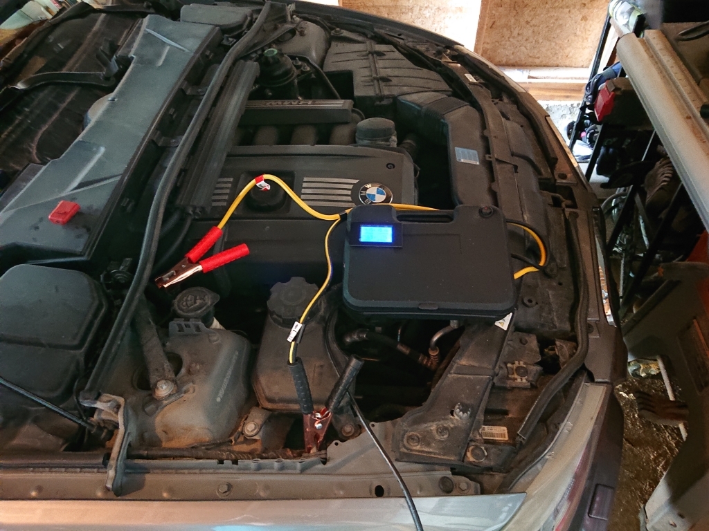 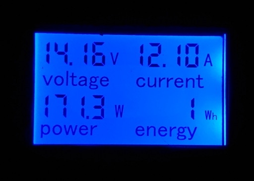 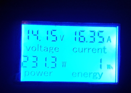 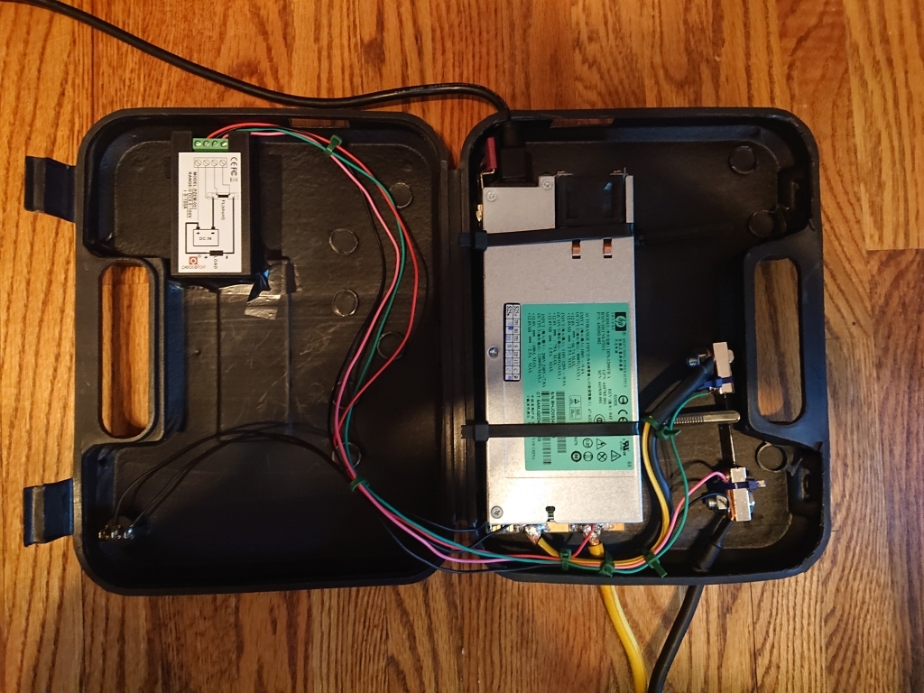 As a Canadian, we are on 120V supply, so this power supply will max out at 75A@12V (64A@14.2V). For those of you living in 220V nations, it will allow the full 100A@12V (85A@14.2V) 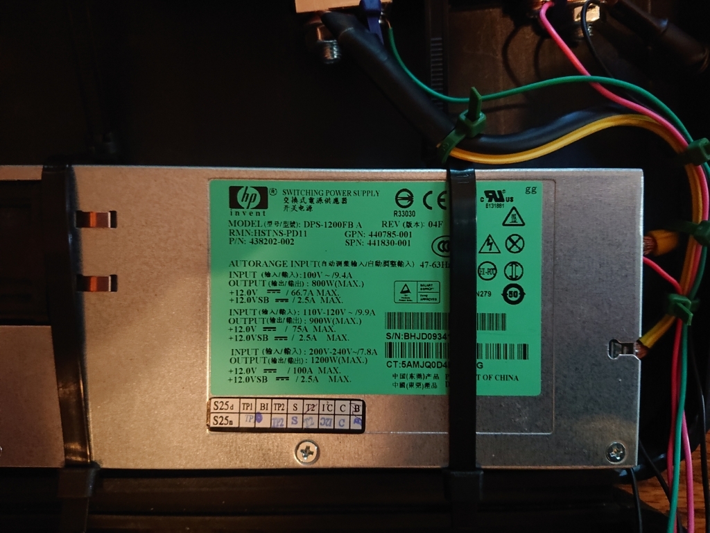 Reference sources: HP DPS-1200FB A HSTNS-PD11 13.8v mod - BMW DIY Power Supply for Programming (HP Server PSU Conversion) - Hardware: $40 - DPS-1200FB from Kijiji $25 - LCD Digital Display Multimeter (6.5-100V, 0-100A) - https://www.amazon.ca/gp/product/B01..._title_o00_s01 $5 - Round Rocker Switch $16 - 8AWG Booster Cables - https://www.canadiantire.ca/en/pdp/m...-0111212p.html $5 - 8AWG Wire Lug Ring Clamps ($5 per pair) $0 - Old Electric Stapler blow molded case $0 - Solid Core wire (Different Colours) $91 - Total Solder a 22k Resister between Pins 33 and 32. A number of references show to just solder a 1k resister between pins 36 and 33, but those pins are wired to weak pull-up or pull-down circuits, so essentially you're fighting between them. 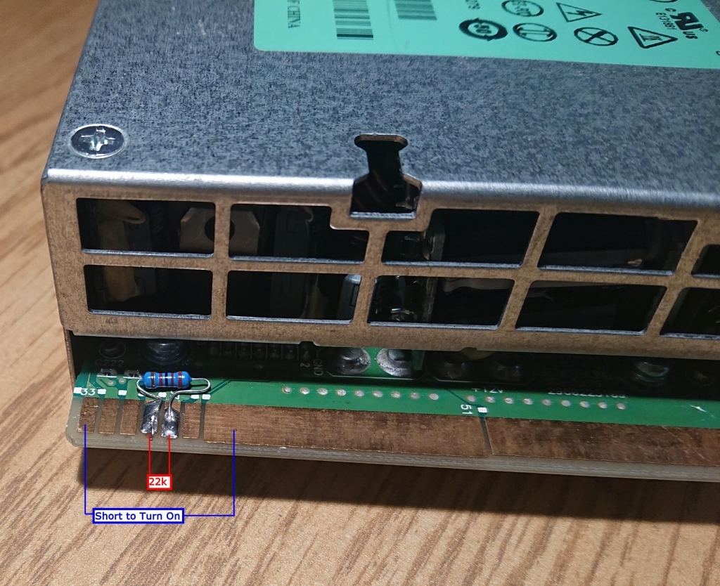 Open up the power supply, the edge circuit board controls adjustment and monitoring. 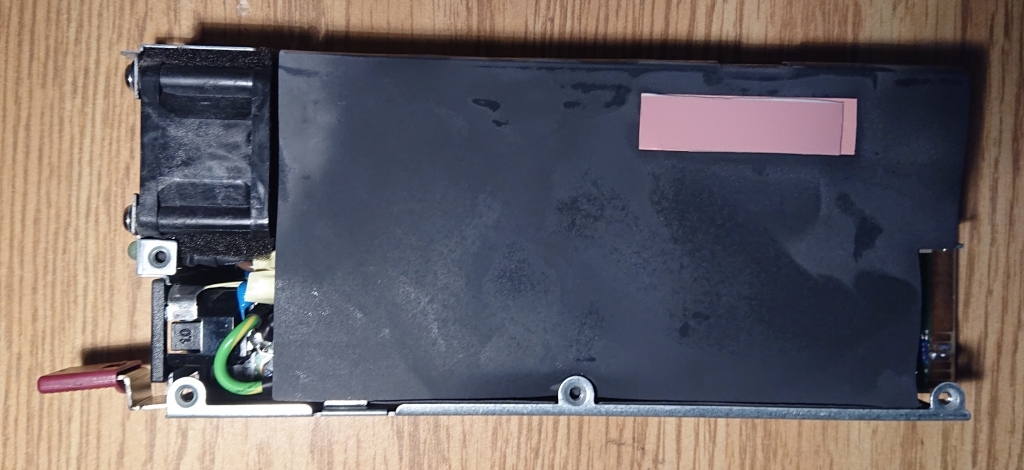 We need to solder 75k and 15k resistors to change the regulation circuitry. By default, the Pot will not adjust high enough and the Over Voltage Protection (OVP) will not allow you to set a 14V output. I didn't have 75k and 15k resistors, but 82k and 18k were close enough to allow me to set the desired voltage. (Note the electrical tape placed between the resistor and circuit board to avoid short circuits. I seem to have misplaced my kapton tape...) 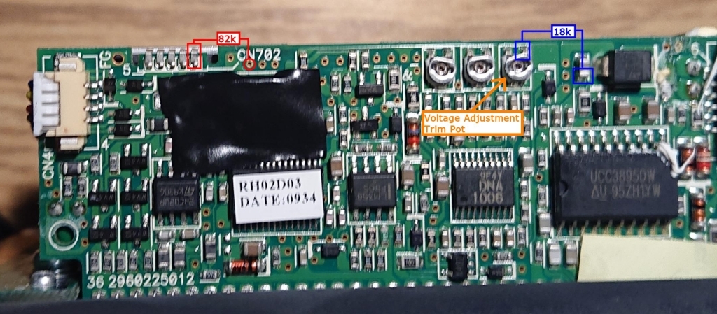 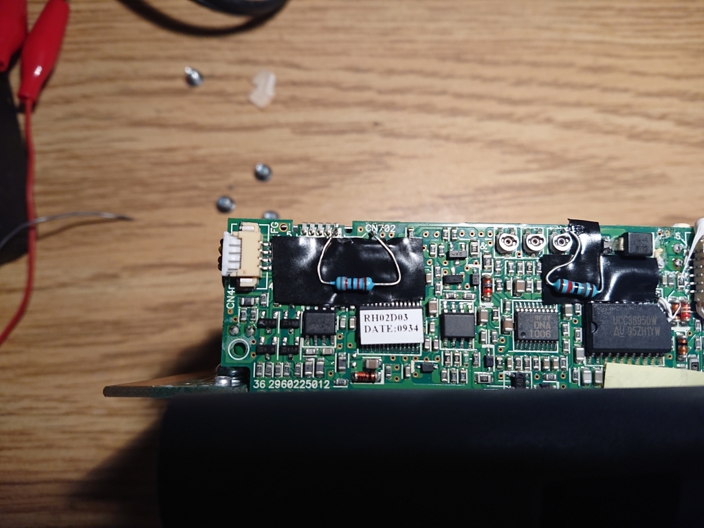 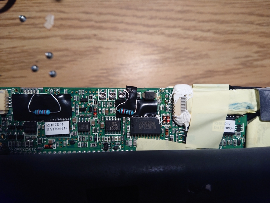 Adjust the pot to get your desired output, I set it to 14.2V, note that this Voltage will drop with a corresponding increase in Amperage. 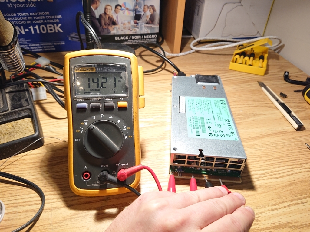 I cut a 1m length of booster cable to wire from the power supply to the clamps. I chose 1m as the booster cables are only 8awg, you can get a larger gauge of cable, but that makes it considerably harder to work with & solder. The SPST rocker switch is simply set up to complete the circuit between pin 36 and ground. This will turn on/turn off the 14V output. Zip ties are used to hold the circuitry in place. Zip ties in the top half are loose, in order to allow the wires connecting the top and bottom half to move as the lid is closed. A hole was cut in the side to allow the power supply fan to vent hot air 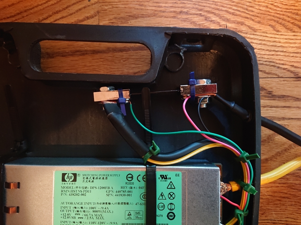 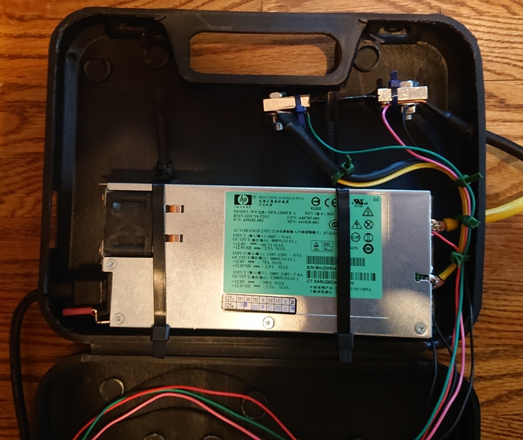 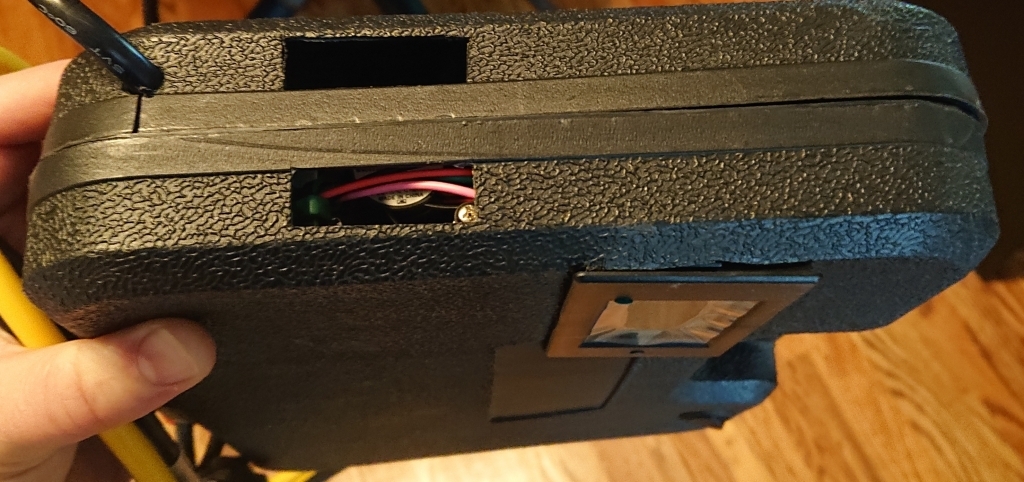 Usage Notes: --- When connecting the power supply, TURN THE POWER SUPPLY ON BEFORE CONNECTING IT TO YOUR CAR. I have not set it up to protect against return path (Car battery powering the power supply), and have not fused it for short circuit! --- The fan will still run, as power is still connected to the power supply. This is ok --- It takes ~20 seconds for the power supply to de-energize the circuits (Capacitors to discharge). Don't touch the clamps together or put the clamps down until the volt meter shows you that you can. 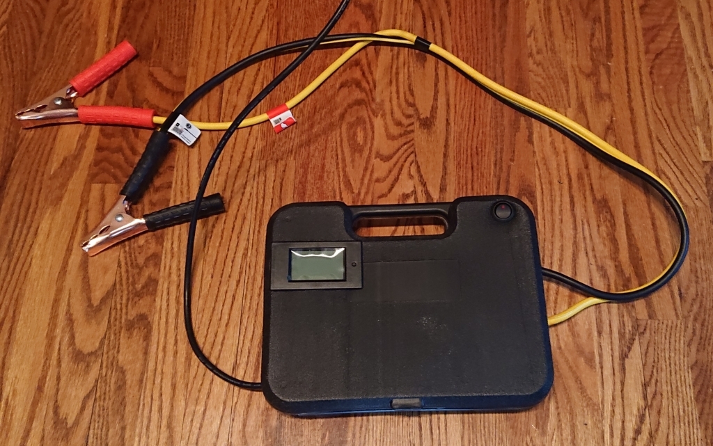 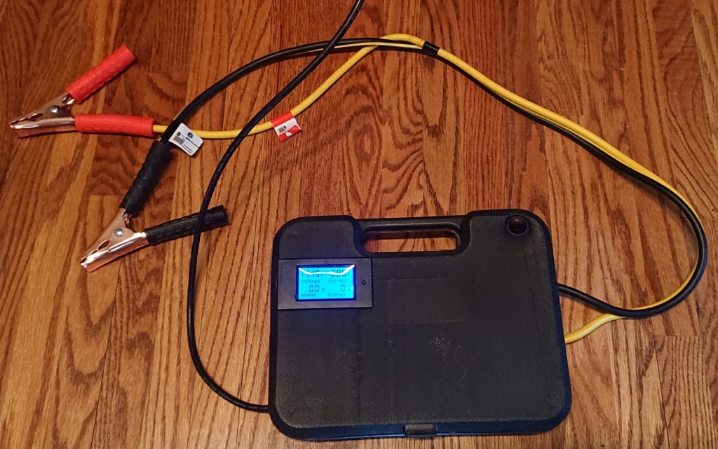 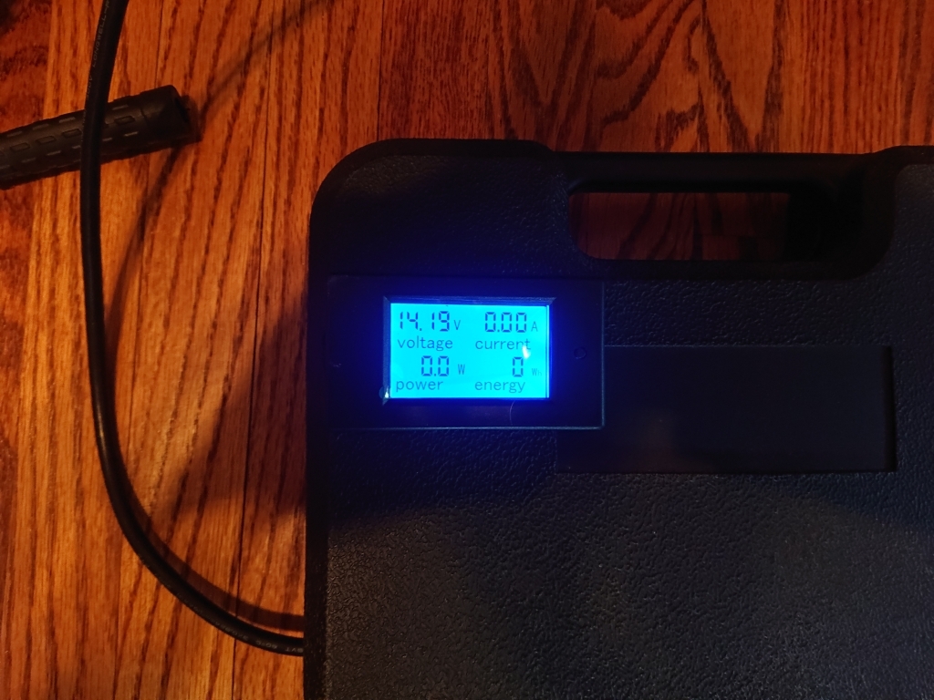 |
|
Appreciate
9
|
| 01-02-2022, 03:52 AM | #2 |
|
Lieutenant
 150
Rep 432
Posts |
Excellent DIY! Thank you
|
|
Appreciate
1
e92m3_ryan1.50 |
| 08-13-2022, 01:13 PM | #8 | |
|
Private
 
21
Rep 73
Posts |
Quote:
Read this again and you will get the point
__________________
...
|
|
|
Appreciate
0
|
| 08-14-2022, 07:46 AM | #9 | |
|
Second Lieutenant

16
Rep 296
Posts
Drives: e92 328xi
Join Date: Jun 2009
Location: Orlando, Florida
|
Quote:
|
|
|
Appreciate
0
|
| 09-19-2022, 06:17 PM | #12 | |
|
Private
6
Rep 82
Posts |
Quote:
|
|
|
Appreciate
0
|
| 09-20-2022, 09:55 AM | #13 |
|
Private
15
Rep 66
Posts |
I almost started building this. But found a used power supply for $100 14.5v 50A and bought it. Guess my point is there are options out there, if someone finds a project like this a bit challenging.
|
|
Appreciate
0
|
| 11-07-2022, 01:54 AM | #15 |
|
Lieutenant
372
Rep 531
Posts
Drives: 2007 E70 4.8i, 2008 E90 335i
Join Date: Jul 2015
Location: Phoenix, AZ area
|
I used a 22k resistor between 36 and 37 which worked for me.
I then added a switch between 33 and ground. That gives me an easy way to turn it on and off. I also 3d printed a case for it that I found on thingiverse. The case was listed for another model but it also fits the PD11 (and other 1200w common slot supplies). The case I printed (I then drilled the side out to add the switch) https://www.thingiverse.com/thing:4871783 A good reference on the startup resistors: http://colintd.blogspot.com/2016/10/...-supplies.html I Have it set to 14v on the meter which reads 13.7 in Ista+. I used 100k and 20k for the voltage adjustment resistors which worked well for me. Trimmed and placed like this doesn't require any extra insulators: Here is the finished unit: I need to print it again because it was one of the first things I printed and I had a shift and warp on it due to adhesion issues when printing in ABS so that it won't melt in the AZ summers if I leave it in the garage. I used a 100amp volt/amp meter from aliexpress and bought a "FL-19 Shunt 100A 75mV Welding Machine Brass Resistor DC Shunts For Current Analogue Panel Meter" as was described by the creator of the case. The current seemed pretty accurate when I did some quick bench testing. I have seen it go to 30amps a couple of times while coding my e90. I bought some nice 4ga "Westin 47-3534 Quick Disconnect Jumper Cable Kit" from ebay for $20 (yes it is a steal and they seem to have more). The kit only has one set of clamps and I cut them off with 1ft or so on the quick disconnect and then shortened the main cable length to 8ft or so and crimped connectors that come with the kit that is intended to be installed on the car to the original cables. Next I used the disconnect that I cut off to crimp to connectors from home depot to connect to the power supply(autozone also has brass crimp connectors for about the same price). This lets me disconnect the cables from the power supply if I want to and it was a nice heavy cable for cheap! I did buy a hydraulic crimper from amazon so it wasn't as cheap after that but even a hammer type crimper would probably have been fine and those are pretty inexpensive. I drilled 3 holes in the connectors for the ground and positive outputs and used some 12ga wire that I had laying around with a connection on each side for each to form the equivalent of a 4ga wire internally. The leads had to be short and it is very much overkill but the connectors didn't cost much. -Rich
__________________
2007 E70 X5 4.8i with 10" android screen Running 265/60/18 AT34s All Terrains (Mainly for road trips)
2008 E90 335i with 10" android screen, 7" intercooler, inlets, Dinan intake, JB4 BEF, E85 conversion, Mfactory LSD, M3 suspension, EDC shocks with custom controller. Last edited by rbryantaz; 11-07-2022 at 02:02 AM.. |
| 12-14-2022, 09:45 AM | #16 |
|
Enlisted Member
 5
Rep 38
Posts |
Hello, I have build the setup just like yours, but with 75k and 15k and 22k ohm resistors, everything is fine, I get 14.28-14.38v (I don't know why it fluctuates) but my question is if is normal the PSU to get hot while running idle. Mine is running idle and is pretty warm after 5 minutes.
This heatsink is pretty hot after 10 minutes of running idle. Last edited by Dragoss91; 12-14-2022 at 09:51 AM.. |
|
Appreciate
0
|
| 12-14-2022, 08:35 PM | #17 |
|
Major
 242
Rep 1,354
Posts |
If you are idling the car with the power supply connected, backflow may come into play particularly if there is no mechanism to handle it.
Both backflow or higher current draw will cause the supply to heat up, possibly to the point of damage. |
|
Appreciate
0
|
| 12-15-2022, 11:20 AM | #18 | |
|
Enlisted Member
5
Rep 38
Posts |
Quote:
The new problem I'm having is the voltage drop when I connect it to the car. I have at least 1,2-1,3 volts drop wich I doubt is normal since I have seen people that have set the PSU to 14,0v and they are getting 13,7v in ista. I have put a 18k resitor on voltage potentiometer and a 22k instead 75k resistor on the OVP so now I can go over 14,39v. I have set the PSU to 14,50v and when I connect it to the car I am having 13,33v after 5 minutes and if I turn on the headlights I am getting 13,21v wich is low in my opinion if for ista is recommended having 13,5. My question is why I have this big voltage drop ? My battery is not low, I was getting 12,2v on IBS normally. May this PSU be old and tired ? Should I replace some capactiors ? All the capactitors are looking good. This is my bimmerlink readings after 15 minutes of run with headlights ON. Also, after 10 minutes the fan went 100%, is this ok ? Later edit: my cables are 2,5 meters long, should be this the cause of this big voltage drop ? Last edited by Dragoss91; 12-15-2022 at 12:06 PM.. |
|
|
Appreciate
0
|
| 12-16-2022, 11:01 AM | #19 |
|
Enlisted Member
5
Rep 38
Posts |
Done, the culprit of the huge voltage drop was the crappy cable, I had 1,3v drop under load. So I dumped them and bought some electric welding machine cables wich are 16mm² good copper and now the drop is 0,03v wich is amazing.
I have set the PSU voltage to 14,01v and I get on car 13,98v, if I turn on the headlights and blower fan to max I get 13,83v wich is quite impressive. |
|
Appreciate
3
|
| 06-09-2023, 05:09 PM | #20 |
|
New Member
0
Rep 5
Posts |
Great post.
I have used one of these contraptions which I built myself for more than a year, without any issues so far. I was able to code all the modules in one go (which can last several hours) on two BMW's. I can confirm it works, but be careful when do the soldering as those parts are very small and they can get de-soldered very quick. Use proper cables as they can get hot after a few minutes. I you can, you can add another fan to the power supply as the one provided is not enough to cool down the power supply.
|
|
Appreciate
0
|
| 06-15-2023, 09:47 PM | #22 | |
|
Lieutenant
372
Rep 531
Posts
Drives: 2007 E70 4.8i, 2008 E90 335i
Join Date: Jul 2015
Location: Phoenix, AZ area
|
Quote:
I think i used 1/4 watt but the main board uses surface mount that are probably even less than that. -Rich
__________________
2007 E70 X5 4.8i with 10" android screen Running 265/60/18 AT34s All Terrains (Mainly for road trips)
2008 E90 335i with 10" android screen, 7" intercooler, inlets, Dinan intake, JB4 BEF, E85 conversion, Mfactory LSD, M3 suspension, EDC shocks with custom controller. |
|
|
Appreciate
0
|
 |
| Bookmarks |
|
|